filmov
tv
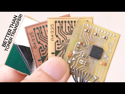
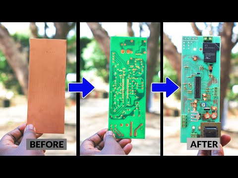
Make your own PCB with a sharpie!

Показать описание
Make your own PCB with a sharpie!
You do not need a fancy milling machine, laser etcher or to send of your CAD designs to the far east. Yes you! YOU! Can make your own PCBs with the aid of a sharpie! (and a few more bits - like ferric chloride and a drill!). But that's it, no fancy CAD, just a steady hand.
Please note: As an Amazon Associate I earn from qualifying purchases. As such links to Amazon products within this video may fall under this. Thanks to all of you who use these links and help support the channel - you are fantastic!
Thanks you lovely people, and keep on tinkering!
Youtube Chapters
0:00 Introduction
 0:10:40
PCB Creation for Beginners - Start to finish tutorial in 10 minutes
 0:10:11
DIY PCBs At Home (Single Sided Presensitized)
 0:09:28
How To Make Custom PCB's For Your Projects!
 0:12:04
Making Professional PCB at Home
 0:05:35
DIY PCB Fabrication (Dry Film Inkjet Method)
 0:32:59
Make your own PCB with a sharpie!
 0:11:05
From Idea to Schematic to PCB - How to do it easily!
 0:10:56
The fastest way to make crisp PCBs at home!
 1:49:10
VCS 2024 Design your own DIY ESP32 PCB controller, David Peace
 0:12:23
You can now PRINT PCBs! Creating a homemade PCB with the Voltera V-One PCB Printer!
 0:08:11
PCB prototyping, PCB making at home - WEGSTR
 0:10:44
Design and Build a PCB - SMD LED Learn electronics engineering
 0:11:24
DIY Making PCB At Home: No Heat Needed! ( Toner Transfer Method )
 0:12:12
DIY PCB Toner Transfer (No Heat) & Etching
 0:04:09
How to Design & PCB Etching- Part 2
 0:06:11
How To Make Your Own Printed Circuit Boards (PCB)
 0:10:04
How to make HIGH quality PCBs at home
 0:03:56
How to make PCB Without Iron, & Added solder mask in PCB trace
 0:45:41
High Quality DIY PCB Boards at Home, Step by Step detailed Instructions (PLUS SMD SOLDERING)
 0:34:27
Make custom PCBs with the Sienci CNC and FlatCAM!
 0:08:51
How to Make A PCB Making CNC in Your Budget
 0:04:22
PCB Manufacturing Process , PCB making
 0:06:18
Design your own PCB with EasyEDA & JLCPCB
 0:14:25
DIY Macro Pad Keyboard Build from Scratch with Custom PCB and Mechanical Switches
Комментарии