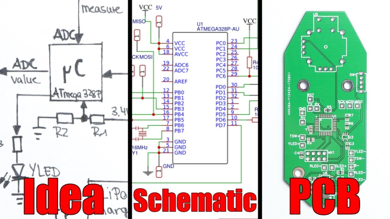
From Idea to Schematic to PCB - How to do it easily!

preview_player
Показать описание

Websites which were shown during the video:

In this tutorial I will show you what steps are necessary to turn your idea for an electronics circuit into a schematic and then into a PCB. Along the way I will show you that it is actually quite simple nowadays to order PCBs from a professional manufacturing house.

Thanks to JLCPCB for sponsoring this video

Music:
2011 Lookalike by Bartlebeats
Killing Time, Kevin MacLeod
Рекомендации по теме
Комментарии
Автор

Step 1: Plan the function of circuit 1:17
Step 2: Component sourcing & paper Schematic 2:18
Step 3: Proper schematic 4:58
Step 4: PCB design & ordering 6:29

syafieqrazak
Автор

You taught me in 11 mins what my Design teacher did not for entire year.. There is a lot of hard work behind your videos...Thank you very much..God bless you.

nickharrison
Автор

Step 0: Know wtf you're doing to begin with.

christucker
Автор

Couple other tips that I've picked up in my time in industry so far is include testpoint vias (and local ground points) on almost all major nets/connections! This will help debugging PCBs by making it easier to pop in scope probes.

Another thing to keep in mind is power domains and signal domains. You usually want to keep these separate as much as possible to prevent interference (Along with some nice ground floods to help isolate fringing fields).

In terms of routing, it always helps to route your major signals first (i.e. RF paths > High Bandwidth Serial Paths > Low Speed Serial Paths > HF Power Paths > LF Power Paths > GPIO Lines > Power) as this will help signal integrity and generally make it easier to route.

LorneChrones
Автор

So THAT'S how it's done! I'd been muddling through this process making all kinds of mistakes and wondering how so many people with a lot less time in electronics than I were able to do it so easily. Nice to finally be able to connect the dots, literally. Thank you for this!

sincerelyyours
Автор

This is officially my favorite video on YouTube. I've always wanted to make my own PCB happen but never had it felt more approachable or attainable than after watching this.

dufric
Автор

0:24 I love how you actually demonstrated soldering SMD parts to a perf board :D

nordemoniac
Автор

An easy rule of thumb you can use for trace widths is 10 mils (0.01") per amp. Then you only need to bust out a calculator for the really high current traces.

Afrotechmods
Автор

90 degrees bends... It's an issue of EMI and wave propagation problem, as well as manufacturing hazard. Electrical wave passing through the copper prefers a straight line, as almost everything in physics. 90 deg bend causes the wave not to propagate properly, some of the signal might be lost or reflected. It may also interfere with other signals in the circuit. This is essential for high speed signaling where you have to keep the trace of the said width to set it to proper impedance so it can match the rest of the circuit. For the manufacturing, the more acute the bend the more risk of resulting track being "over-etched", which means being thinner than expected. With thin tracks it could lead to bad signal integrity best case and an open circuit worst case.

The other thing is that a good practice is to make the supply voltage traces as thick as possible for low inductance and low voltage drop across the trace, especially with currents closing to 1 amp and above.

timen
Автор

i've studied electronics, i practiced at a company which repaired TVs (among other things) - the beginning of the plasma screen era, the first SMDs appeared back then - and I was never taught that I could solder SMDs with hot screwdriver (only the hot air gun, - they said - method was possible! which...i never advanced enough to be tought that..)
impressive & informative video!!
thank you 👏

sadderwhiskeymann
Автор

I am loving JLCPCB! From part picking, to schematic, to layout, to ordering the PCB and BOM.. all super seamless and easy! I'm not even getting paid for this, but I am really digging it. Glad I saw this.

poppatang
Автор

I started doing contract work, designing and constructing test equipment. But I was stone broke. So every software I used, was freeware. The PCB design freeware software was limited to a small number of electronic components, such 8 pin IC's, 1/4 resistors, etc., unlike the costly version. This limited number of components per PCB layout, was far below the number that I typically required. However, it did also allow you to design your own custom components. So I would design a portion of the PCB, and once I was happy with the layout of that portion, I would now turn this section into a single component. So, I was now back to having used only one component. It took a bit of work, but this trick got me to eventually complete the PCB layout.

new-knowledge
Автор

I have not any experience with ICs; the most I've messed with circuits is soldering some LEDs, BUT you always get to keep me through the video and I actually think I understand most of it. Well done and thank you truly! You're an example of a content creator!

PGrimp
Автор

I have actually made my very own PCB with this tutorial, and it has worked the first time off. Not too complicated but it is great to see your design worked first shot. I have since made revisions 2 and 3 to improve on my design. And bonus, it looks professional.

AJRestoration
Автор

I'm an electrical engineer and i love your videos. never stop

majorzeros
Автор

Seriously, this is one of the best videos on PCB design. I am proud to be your patreon. Keep it up!

rklauco
Автор

"trust me, I'm an engineer" 0:25

the_legend_
Автор

I don't know about anyone else but 'Let's get started!' for me means have a few deep breaths, stretch a little, chill, tune in and carry on watching and I'm not even majorly into electronics, I just like the art & craftiness of it all!

reggiep
Автор

My eyes hurt when you soldered that SMB IC to the perfboard :'D

Автор

they never taught me any prototyping in my mechatronics course, thank you for doing the work my school failed to do

Apocobat