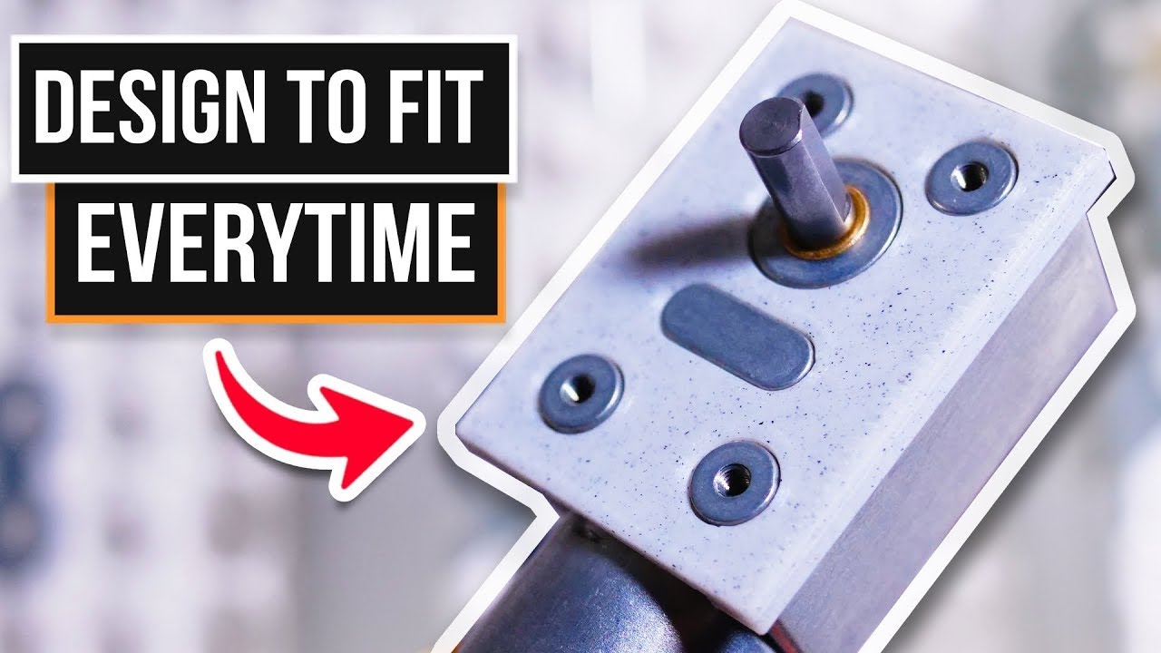
My Secret To Perfectly Fitting 3D Prints

preview_player
Показать описание
Unlock the secret to perfectly fitting 3D prints with my little trick! Dive into precision modeling in Blender, learn how to leverage scale reference, and transform any photo with just a ruler into accurate design. So if your a maker or hobbyist, this tutorial is your gateway to flawless 3D printing results.

MAKER TALES ACADEMY
- - Learn Blender Fast Through 3D Print Design Paid Course - - -

Useful Links:

MAKER TALES ACADEMY
- - Learn Blender Fast Through 3D Print Design Paid Course - - -

Free Course | Learn Blender 2.9+/3.0 through precision modelling playlist:

If you have any questions please leave them in the comments below and I'll do my best to get back to them as soon as I can or even better join the discord and I'll be sure to see it.

💬 Maker Tales Discord Server

🛠 Subscribe To Keep Making:

📨 Share with a friend:

📺 Watch My Most Recent Upload:

Other Places Where you can find me:
Рекомендации по теме
Комментарии
Автор

This makes sense for layouts, curves, complex shapes. But for the diameters of those cylinders, hole distances, etc. I think it's still better to use a caliper.

m
Автор

Took me a long time to figure out the "as far away as possible" photo trick... this makes a huge difference

jeremiahbullfrog
Автор

If you have a scanner, you don't only get a perfectly orthographic photo, you also get a fixed scale. So if you can, use a flatbed scanner.

Thomas_Lo
Автор

A major cheat to copying in a pre-existing item is to remember that any patterns are probably symmetical and dimensions are often the usual sorts of numbers that designers are wont to pull out of the air. So in something like this, the bolt holes will be on a fixed grid (ie the lines between them will be parallel and perpendicular to each other) and probably at multiples of 5mm apart. In the same vein, corner fillets are often 5mm or 10mm radius. While I've used the photo method, I've also drawn up all sorts of things to match something with nothing more than a ruler.

smorris
Автор

Useful stuff! Some thoughts:

1. When initially measuring, make sure to do so in both Imperial *AND* Metric. (If measuring in Imperial and the last two decimal digits is close to a multiple of 25, that is a good sign that the part was designed with Imperial measurements.)
2. Don't waste time and materials when testing fits. A thin plate on a raft with holes in it--as he used here--is all you need to check initial fitting.
3. Unless you are doing a one-off, don't bother fiddling with your phone to scan the part in. Instead, pick up a cheap-as-chips scanner or all-in-one from your local classifieds. You won't have to worry about zooming/etc, and everything will be perfectly aligned.
4. Print a precisely-sized rectangle larger than what you need to scan, cut a rough hole in the center big enough for the object--without touching the rectangle, of course, then lay both on the scanner, facing downwards. You can then accurately scale the image using the high-contrast rectangle instead of the object, itself.

Cheers!

KeithOlson
Автор

In Fusion 360 you can calibrate that imported image - you choose two points and enter what distance this is. Not aware of other CAD software, but in Fusion it's very simple. For me making a simple model (as shown in the video) is faster with calipers, but your method is great while working with odd shapes, curves etc.

dismayer
Автор

Very interesting. Maybe you can shoot your ruler at the same time as the object, that should simplify the scaling.

TitouFromMars
Автор

A flatbed scanner also works well if the face is pretty flat and doesn't have an axis pointing out the bottom.

darrennew
Автор

other really easy workflow; check for manufacturer documentation. Especially for technical elements, like stepper motors, sliprings, etc. They usually have a technical drawing somewhere with the exact dimensions on it for everything.

fladder
Автор

0.2 mm is the difference between press fit and loose fit. I use this technique for low-accuracy work. However, when precision is needed I break out the calipers

Hilmi
Автор

Great idea on using background compression. For the photo, I’d suggest using a cutting mat that has either a 1cm or 1/4 inch grid on it. Place the object on it and you have the X and Y scale right there.

Rathgood
Автор

Hey just a wee thank you for the orthographic photo trick, never would've considered doing it - take a gold star sticker for your jotter ⭐

-AT-WALKER
Автор

For fitting round parts I usually print a small wall 5mm high and try it from there. The repeat accuracy of these printers is actually quite good.

julianweiser
Автор

I've done something very similar using a flatbed scanner for parts that can be scanned. If you only care about a flat part on the end, the scanner will scan the portion of interest with 2400 dpi resolution and the portion above the scanner bed will be fuzzy and out of focus. The scanned image can be opened in GIMP, which has tools that can measure any dimensions you like with sub-pixel accuracy. A scanner and GIMP is a very inexpensive optical measuring system, similar to having a microscope with built-in micrometer.

I use a scanner and GIMP for determining the hardness of a material using the Brinell method. A hard ball is pressed into the surface using a fixed force. The diameter of the spherical impression indicates the hardness of the material. I scan these small impressions at 2400 dpi and GIMP can make six measurements of the diameter at different angles, with sub-pixel accuracy. I average the measurements. It's far more accurate than using an optical scale on a pocket magnifier.

LibertyEver
Автор

Tip: you can default transforms like position and rotation by pressing alt + transform key (like "S" for example, resetting the scale to 1). This helps save a little time while dragging the image in as a plane; you can set it to be in the world center and lay flat using alt + "G" and alt + "R".

MilesFinder
Автор

This works. Needed to make a riser for a pet food water bowl and the orthographic photo method did the trick. Thank you!

EDGeProjects
Автор

I feel dumb asking but Im a blender n00b. At 2:30 you took the cylinder, bisected it, and extruded half into an oblong shape. For the life of me, I've tried figuring this out. How is that done?

EDGeProjects
Автор

this is genius and the delivery is perfect. Thanks a ton

markjr
Автор

Nice trick for programs like blender. In oneshape or other cad software this works aswell. But i do prefer just measuring and inserting those numbers in my cad software.

CmdrMartinThompson
Автор

I usually prefer working with OpenSCAD instead of blender. But a similar workflow is possible! Import the photo into inkscape, create a simple SVG with outlines of your part (to scale) and then import that into OpenSCAD as a 2D primitive. Boom!

ironnoriboi