filmov
tv
SINGLE PHASE MOTOR CONNECTION WITH MAGNETIC CONTACTOR WIRING DIAGRAM

Показать описание
Single phase motor connection with magnetic contactor wiring diagram
A single phase motor is an electrically powered rotary machine that can turn electric energy into mechanical energy. it works by using a single phase power supply. they contain two types of wiring hot and neutral.
magnetic contactors act as a safeguard to protect the power supply and the motor.
(MCB) Miniature Circuit Breaker
Miniature Circuit Breaker MCB automatically switches off electrical circuit during an abnormal condition of the network means in overload g condition as well as faulty condition.Now days we use an MCB in low
 0:07:42
How to Connect a Single Phase Motor
 0:07:19
Single Phase Motor Reverse Forward Connection || Motor Connection @TheElectricalGuy
 0:03:06
SINGLE PHASE MOTOR CONNECTION WITH MAGNETIC CONTACTOR WIRING DIAGRAM
 0:03:28
single phase motor connection with magnetic contactor wiring diagram
 0:01:29
Single Phase Motor Wiring | Single Phase Motor Connection with Switch | House Wiring |
 0:04:27
Single Phase Motor Connection with Magnetic Contactor / Single Phase Motor Control Wiring Diagram
 0:04:30
Single phase motor wiring with 2 capacity-reverse and forward
 0:00:51
Double capacitor motor connection #shortsfeed #connection #doublecapacitar
 0:01:17
Single Phase Motor Connection with Two Capacitors | Double capacitor motor connection
 0:04:06
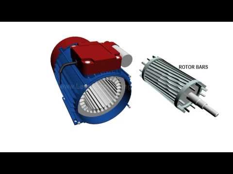
Single Phase Induction Motor, How it works ?
 0:12:20
How Motors Work For Beginners: (Episode 4) Single Phase Induction and Shaded Pole Motors: 035
 0:06:17
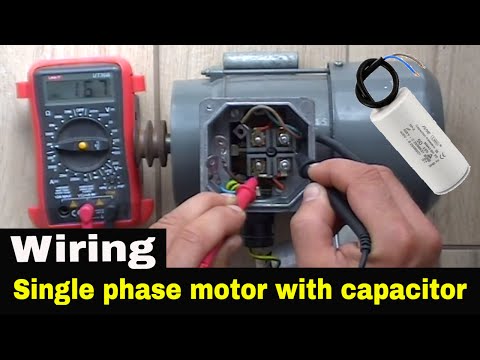
How to wire single phase motor with start/run/permanent capacitors.
 0:00:40
Single Phase Motor Connection with Two Capacitors | capacitor start capacitor run motor ।
 0:07:52
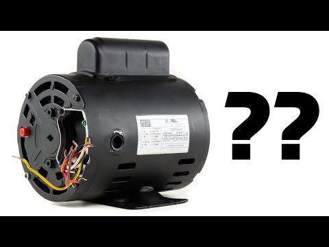
Single Phase Electric Motor Wiring Tutorial: Baldor, WEG, Leeson
 0:01:39
How to connect a single phase motor with two capacitor || Azan Electrical
 0:02:35
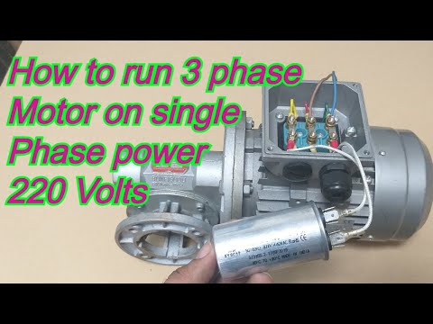
How to run three phase motor with single phase Supply
 0:07:26
Single Phase Motor Connection with Two Capacitors |@ElectricalTechnician
 0:15:25
Single Phase Direct Online Starter DOL Wiring Diagram Connections Explained - AM2, AM2S, AM2E
 0:00:19
CSQ single phase motor connection with magnetic contactor & MCB wiring diagram
 0:02:22
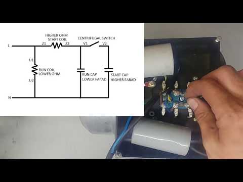
Single Phase Motor Runing Capacitor Start Capacitor Centrifugal Switch Connection | It's Electr...
 0:07:48
Single Phase Induction Motor Connection | Motor Connection with Capacitor @LearnEEE
 0:03:02
Single Phase Motor Reverse Forward Connection || Reverse Forward Motor Connection || It's Elect...
 0:04:53
TESTING SINGLE PHASE MOTOR USING A MULTIMETER
 0:06:56
Connecting a 3 phase motor with 1 phase Power with Diagram
Комментарии