Chinese mini welder display adjustment ZX7-250 MINI

preview_player
Показать описание
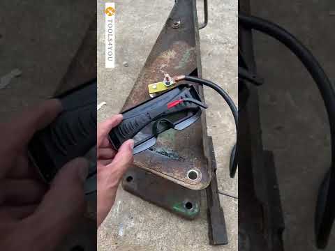
I bought this welder on BangGood. In the reviews, it was both praised as welding well but also criticized for having a false current rating. According to one review, its max current is around 120amps. This is fine for what I bought it for, so I won't have to fire up and drag out the huge, three phase, Czechoslovak transformer welder I have for just some small job.

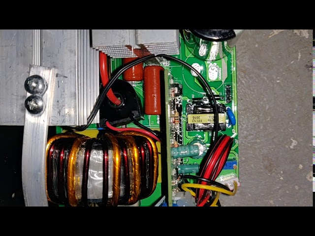
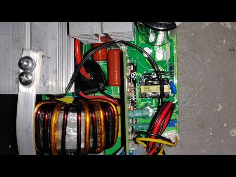
But I'm annoyed that the LED display is totally false. Fortunately this is easily fixable by adjusting one varistor which sets the range of the display.

Also, I point out in the video the 180 amp fusible link, which definitely puts to rest any question whether this thing was meant to out out 250 amperes.
Рекомендации по теме
Комментарии
Автор

I have 2 of these welders. I figured out you have to correct the digital readout with a 3 resistor bias circuit using the independent supply of the meter. I used a constant resistor with two trimmer potentiometers to build a mini circuit board to correct the reading on the meter to match the actual amperage of the welder. The other trim pot you mention that you do not know what it does controls the output amperage of the machine. Yes mine to has a 180 amp circuit breaker on the buss bar, do not think that is obtainable with the circuity provided by the Chinese. I am setting mine up to run at about 130 to 140 amps then will use the bias circuit to adjust the meter reading. Also if you really want more amperage take 2 of these machines and connect them in parallel and you can run much bigger rods up to 225 amps. However with two machines running at high frequency the welding sound starts to have a high pitch noise to it in lieu of the normal frying bacon sound. If anyone needs more detail on this bias circuit I will be happy to converse with you. Thanks

russellmatheny
Автор

This is awesome info!!!! Thanks. I have my welder which I hooked up to an independent shunt with amp and volt meter to get the actual output. They said 225 amps and it actually was about half of what they said. So finally I found your viedo that shows me how to trim or adjust the digatal meter to match what the welder is putting out. Thanks Again!

russellmatheny
Автор

ATTN: IF I had my own YOUTUBE channel, I would make a video about this
DEFECT I found and corrected in my brand new TopShak ZX7-250A 110V
welder, which I bought on Banggood. Apparently, this unit was assembled
using five M3x10 machine threaded screws to anchor the 3 big heat sinks
in the back of the unit, near the cooling fan. This was a HUGE MISTAKE
on the manufacturers part, because the heat sinks have no machined or
tapped threads for the M3 x10 anchoring screws to bite into, but only
SLOTS in the aluminum castings. You need to grab a standard #2 Phillips
screwdriver and remove the welder cover, then use the screwdriver to
check all five heat sink anchoring screws on the bottom of the circuit
board, to see how many of them are loose and INCAPABLE of even being
sufficiently tightened in the first place. I just replaced all five heat
sink anchoring screws with some slightly bigger cabinet screws, which
have tapered threads that are very similar to self tapping screws. NOW
all five screws can be tightened very securely. You really don't want
any of those 3 heat sinks EVER coming loose, because the result will
eventually be a certain failure of the welder. ALSO....the word VARISTOR should NOT be used to describe ANY type, style or size of variable resistor or potentioemeter, because a VARSITOR is a completely different kind of electronic component.

scottfrazer
Автор

the problem, it is not linear, min value in real is 54 A (shown as 24A), 66 on display is 68A real, but 204 on display is 113A. we need to correct low and high amps

vitaliryumshin
Автор

Good video, thanks. Check the metal case for earth connection. My one came with a three core flex with earth wire but the earth was not connected inside the box.

piclife
Автор

TOPSHACK ZX7-250. I replace fixed resistor 6K8 with 3K. LCD now shows 145A MAX. This is Ok.

SuperDTMF
Автор

the first version was better, it had 3 capacytors, and the voltage adjust is on the main board lower end, i have it at 150 (with a shunt amp meter it maxed about 130A)

fp
Автор

They mostly barely get 110amps but theyre fantastic. I wish i had the cash to get skids at the time i first bought them, coulsve made alot because noone had them in Australia. Now the big name brands are selling these. With small mods can achieve 180 amps stable but dont use 3.2 rods they go bang. 2.4 is ok

djisydneyaustralia
Автор

Thanx for reply. Now I realize that I have used another potentiometer. Your set up for max current on display works. Now I have window from 14 to 139. I will continue to find how to lower output current to cca 40 A.

zeljkozeljeznjak
Автор

I can't see where you crew on board,
Could you show us pls?

josesplana
Автор

A 180 amps fuse is totally unnecessary and a waste of money for this kind of low cost machine. In my inverter such part is a current shunt for measuring the output (in the pcb there are the sense lines from the shunt to the measurement circuit). Very interesting video

tecnology-today
Автор

Will you please inform me where I can get the same machine circuit board

kunnathupadickalmanoharan
Автор

Hi good day to you sir can you share to me what pwm ic number does the zx7 use in control board because my problem was their is no pwm signal going to igbt

johnjeronepenaflor
Автор

good night friend, could you check the values ​​of resistors R4, R5, R8 and R9 on this board, they control the IGBT

danielsouza
Автор

One pots is for display and the other is for output current .

dusanmilojevic
Автор

Thanks for your review and the info you shared. Very helpful and important

dionisiosciascia
Автор

wasnt that fusable link for inupt not putput

nunyabidness-qrvp
Автор

Its simple, two IGBT 60Amp, max pulsed collector current 180A, max 428Watts what to expect if it fits in the palm of your hand? 🙂

weldyboy-R-
Автор

I didn't see it... video is dark...

pearllen
Автор

I tried to repeat your test, but with my welder it doesn't work that way. The display changed by 1-2 units, but the output current changed considerably. So far the max output current was 129 and now I have set it to 150 A. I have not tried further. Min remained the same 55 A. I would like to lower that to about 35 -40 A, but I don't know how.

zeljkozeljeznjak