filmov
tv
Con rod - Can you work it out?

Показать описание
Just for the crack - have at it in the comments
Thanks to all my patreon subscribers. If you wanna help out go here -
Paypal link -
Join me on facebook if you wanna ask question, all bike/engine related questions are welcome -
Thanks to all my patreon subscribers. If you wanna help out go here -
Paypal link -
Join me on facebook if you wanna ask question, all bike/engine related questions are welcome -
 0:11:27
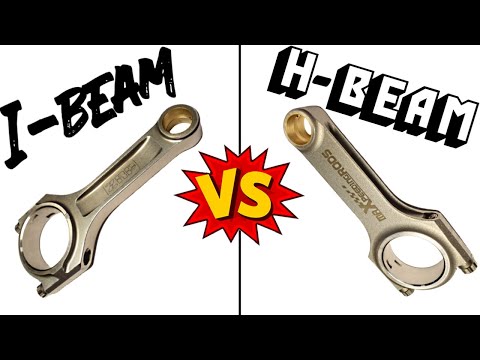
H Beam vs. I Beam CONNECTING RODS
 0:06:38
H Beam vs I Beam Connecting Rods | Which is For Your Build?
 0:09:21
Con rod - Can you work it out?
 0:00:58
Stock vs Race Piston Rods
 0:05:31
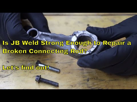
Is JB Weld Strong Enough to Repair a Broken Connecting Rod? Let's Find Out!
 0:00:59
Mr. Gasket Connecting Rod Vise
 0:00:08
Engine connecting rod fitment 😳😀 #shorts
 0:06:26
How to Choose the Right Connecting Rods
 9:33:38
🔍 The Adventures of Sherlock Holmes 🕵️♂️ | A Classic Detective Mystery by Arthur Conan Doyle...
 0:00:11
Remove Connecting Rod Bushings
 0:00:10
#Engine tips #Mark the big end bearings & connecting rod if you need to reuse the big end bearin...
 0:00:41
Rod KNOCK Test For Bad Bearings
 0:00:15
Resurfacing my crankshaft after two spun rod bearings - Mitsubishi Eclipse GT V6 6G75
 0:05:34
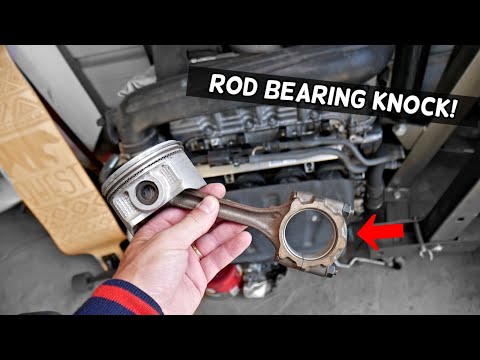
WHAT ROD BEARING KNOCK SOUNDS LIKE
 0:07:36
What is a Fractured Connecting Rod? Cracked Rod? Advantages and Disadvantages.
 0:00:08
Motorcycle Engine Bad Noise. #shorts #shortvideo #ytshort #crankshaft
 0:00:42
What Is A Spun Rod Bearing
 0:00:30
Big End Bearing Knock or Rod Knock Example
 0:18:43
MIND BOGGLING ENGINE GEOMETRY - Rod Ratio Explained
 0:00:54
What Are the Pros and Cons of Fracture-Splitting Connecting Rod Technology #car #engine #mechanic
 0:00:22
DIY Connecting Rod Wrist Pin Installation Tool
 0:02:15
Why You Should Machine Your Connecting Rods
 0:00:36
How to Fix a rod Knock on any Engine!!!
 0:00:16
Sounds like a Rod Knock noise, but it's NOT. Get a second opinion for the Repair
Комментарии