filmov
tv
MIND BOGGLING ENGINE GEOMETRY - Rod Ratio Explained
Показать описание
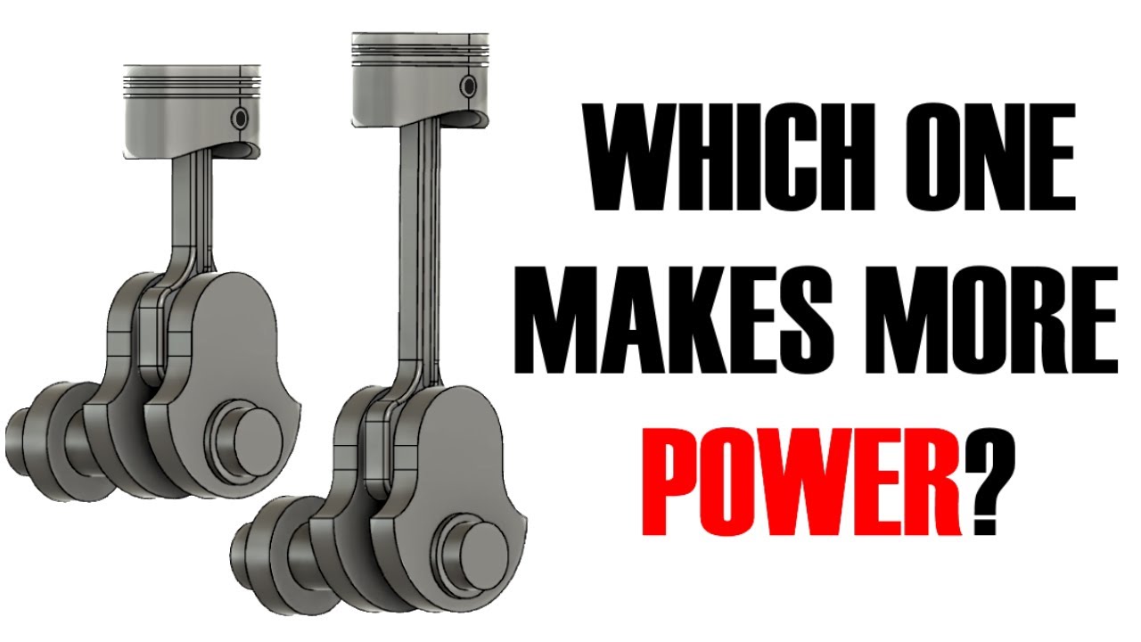
Here we have two engines. Both have the same bore and the same stroke. As you can see the only difference is the length of their connecting rods. At the same engine speed so at the same speed of rotation, the same rpm. Which engine has a faster accelerating piston?
As you can see the question I asked you was a trick question because the piston in the short rod engine accelerates faster from top dead center going down while the long rod piston accelerates faster from bottom dead center going up. So why does this happen if both engines have the same bore, same stroke and are obviously spinning at the same rpm. Well the culprit behind is obvious. It's the connecting rods, as they're the only thing different between the two engines. And this video I promise to strain your mind to the redline by explaining how something as simple as different connecting rod lengths create different piston acceleration and then using real life engine examples we will see how this impacts everything from power and torque to engine longevity, responsiveness, vibrations and even things like coolant temperatures.
So these two engines have different rod lengths, this means that they have different rod ratios. The full name is actually rod to stroke ratio. And it's the ratio of the center to center length of your connecting rod to the length of your engine's stroke which is determined by your crankshaft.
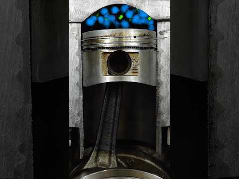
A connecting rod is essentially a fixed length line. It's absolute length obviously never changes. But the relative length of the connecting rod is constantly changing when the engine is running. In other words the connect rod length changes in relation to the piston and the crankshaft as the engine is running.
At top dead center and as you can see the connecting rod is fully upright. In this state it's at its maximum length in relation to the piston and crankshaft. Now as the engine rotates towards 90 degrees the connecting rod assumes it's fully angled position. In this position it is obviously at it's shortest in relation to the piston and the crankshaft. As we said an angled line has a shorter relative length than that same line when fully vertical.
So as the engine rotates from 0 to 90 degrees the connecting rod is becoming shorter in relation to the piston and the crankshaft. As it does so it pulls down the piston an additional distance. The piston is already traveling downward so adding distance in the same direction forces the piston to accelerate more to cover that added distance.
In fact we can observe this con-rod added distance in practice on every single piston engine ever made. Simply take any engine and rotate it to 90 degrees, or to half the stroke. Obviously at half the stroke the piston should also cover half the stroke distance? But it never does, at 90 degrees of rotation the piston of every engine will have traveled beyond half the stroke. This additional distance is the distance added by the connecting rod as it's relative length shortens.
So why does the piston in the short rod engine accelerate more? The reason is simple and it's that a shorter rod length in relation to the same stroke results in the connecting rod assuming a steeper angle against the piston and crankshaft centerline. The steeper the angle the shorter the rod becomes in relation to the piston and crankshaft.
So now we understand why the short rod piston accelerates faster away from TDC and we can use the same principles of relative rod length to understand what happens throughout the entire engine revolution.
Now let's look at the rod ratios of some real life engine examples to see how these differences in acceleration actually impact the engine.
Our first engine is the 1.6 liter Hyundai Gamma engine as found in numerous different Hyundai and Kia vehicles. As you can see this your typical daily driver engine with a modest redline, decent power and a pretty low rod ratio.
Next up we have the 2 liter Honda K20 engine. We're looking at the performance version of this engine and as you can see it makes quite a bit more power than the Hyundai engine and it also has a noticeably higher redline and also a higher rod ratio.
Our final engine is the one from the 2013 to 2018 Kawasaki ZX6R. As you can see it makes impressive power for it's very small displacement and has a redline that's almost twice that of the Honda K20. It also has by far the highest rod ratio. Somewhere around 2.2 or 2.3 is the highest realistic rod ratio for mass produced engines. Some of the highest rod ratios were found in Formula 1 cars at about 2.8
A special thank you to my patrons:
Daniel
Daniel Morgan
Pepe
Brian Alvarez
Jack H
Dave Westwood
Joe C
Zwoa Meda Beda
00:00 Piston acceleration in detail
09:40 Rod ratios of real engines
#d4a #rodratio
As you can see the question I asked you was a trick question because the piston in the short rod engine accelerates faster from top dead center going down while the long rod piston accelerates faster from bottom dead center going up. So why does this happen if both engines have the same bore, same stroke and are obviously spinning at the same rpm. Well the culprit behind is obvious. It's the connecting rods, as they're the only thing different between the two engines. And this video I promise to strain your mind to the redline by explaining how something as simple as different connecting rod lengths create different piston acceleration and then using real life engine examples we will see how this impacts everything from power and torque to engine longevity, responsiveness, vibrations and even things like coolant temperatures.
So these two engines have different rod lengths, this means that they have different rod ratios. The full name is actually rod to stroke ratio. And it's the ratio of the center to center length of your connecting rod to the length of your engine's stroke which is determined by your crankshaft.
A connecting rod is essentially a fixed length line. It's absolute length obviously never changes. But the relative length of the connecting rod is constantly changing when the engine is running. In other words the connect rod length changes in relation to the piston and the crankshaft as the engine is running.
At top dead center and as you can see the connecting rod is fully upright. In this state it's at its maximum length in relation to the piston and crankshaft. Now as the engine rotates towards 90 degrees the connecting rod assumes it's fully angled position. In this position it is obviously at it's shortest in relation to the piston and the crankshaft. As we said an angled line has a shorter relative length than that same line when fully vertical.
So as the engine rotates from 0 to 90 degrees the connecting rod is becoming shorter in relation to the piston and the crankshaft. As it does so it pulls down the piston an additional distance. The piston is already traveling downward so adding distance in the same direction forces the piston to accelerate more to cover that added distance.
In fact we can observe this con-rod added distance in practice on every single piston engine ever made. Simply take any engine and rotate it to 90 degrees, or to half the stroke. Obviously at half the stroke the piston should also cover half the stroke distance? But it never does, at 90 degrees of rotation the piston of every engine will have traveled beyond half the stroke. This additional distance is the distance added by the connecting rod as it's relative length shortens.
So why does the piston in the short rod engine accelerate more? The reason is simple and it's that a shorter rod length in relation to the same stroke results in the connecting rod assuming a steeper angle against the piston and crankshaft centerline. The steeper the angle the shorter the rod becomes in relation to the piston and crankshaft.
So now we understand why the short rod piston accelerates faster away from TDC and we can use the same principles of relative rod length to understand what happens throughout the entire engine revolution.
Now let's look at the rod ratios of some real life engine examples to see how these differences in acceleration actually impact the engine.
Our first engine is the 1.6 liter Hyundai Gamma engine as found in numerous different Hyundai and Kia vehicles. As you can see this your typical daily driver engine with a modest redline, decent power and a pretty low rod ratio.
Next up we have the 2 liter Honda K20 engine. We're looking at the performance version of this engine and as you can see it makes quite a bit more power than the Hyundai engine and it also has a noticeably higher redline and also a higher rod ratio.
Our final engine is the one from the 2013 to 2018 Kawasaki ZX6R. As you can see it makes impressive power for it's very small displacement and has a redline that's almost twice that of the Honda K20. It also has by far the highest rod ratio. Somewhere around 2.2 or 2.3 is the highest realistic rod ratio for mass produced engines. Some of the highest rod ratios were found in Formula 1 cars at about 2.8
A special thank you to my patrons:
Daniel
Daniel Morgan
Pepe
Brian Alvarez
Jack H
Dave Westwood
Joe C
Zwoa Meda Beda
00:00 Piston acceleration in detail
09:40 Rod ratios of real engines
#d4a #rodratio
 0:18:43
MIND BOGGLING ENGINE GEOMETRY - Rod Ratio Explained
 0:15:50
COMPRESSION RATIO: HOW to CALCULATE, MODIFY and CHOOSE the BEST one - BOOST SCHOOL #10
 0:23:45
Cylinder Offset Changes Everything
 0:06:28
Rod Ratio - Dyno tested
 0:00:56
How Engine Balance Shafts Work (In 60 Seconds)
 0:00:07
What did one petrosexual say to the other? #engine #fourstroke #engineering #car #jdm #tesla #ev
 0:00:19
New video on the channel! #d4a #boostschool #anti-lag
 0:00:36
Secondary forces visualized #d4a #engine #engineering #piston #mechanical #toyota #yamaha #honda
 0:05:13
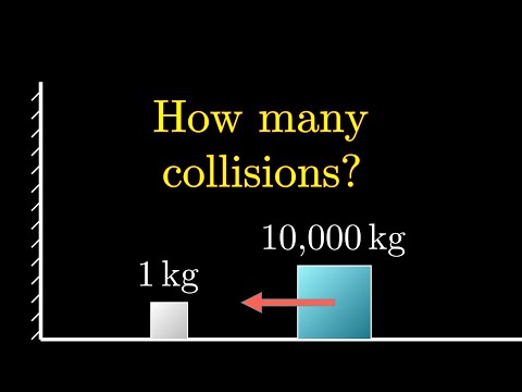
The most unexpected answer to a counting puzzle
 0:00:48
Effect of changing conrod length (rod/stroke ratio) sort of. Not a firing order video. 300RPM
 0:01:00
Torque VS Horsepower
 0:00:07
Opposed Piston Opposed Cylinder Engine| OPOC Engine #cad #mechanical #automobile #automotive #3d
 0:00:07
stroke engine in yamaha #shorts
 0:00:18
V4 engine with strong power
 0:00:10
mind boggling
 0:54:49
WK1. Engine Components, Geometry and Operation
 0:10:47
Internal Combustion Engines: Engine Geometry | Dr. Samer Ali
 0:00:58
Stock vs Race Piston Rods
 0:00:57
Connecting-Rod Length Comparison #shorts
 0:01:00
Here's Why Stroke Creates More Torque Compared to Bore 🤯
 0:00:14
1RZ Engine Connecting Rod
 0:00:06
Which is better Piston Cylinder Arrangement? #engine #mechanical #mechanism #solidworks #3ddesign
 0:00:56
How to Choose The Right Pistons
 0:17:36
Ancient Aliens: Da Vinci's MIND-BLOWING Secrets Revealed
Комментарии