filmov
tv
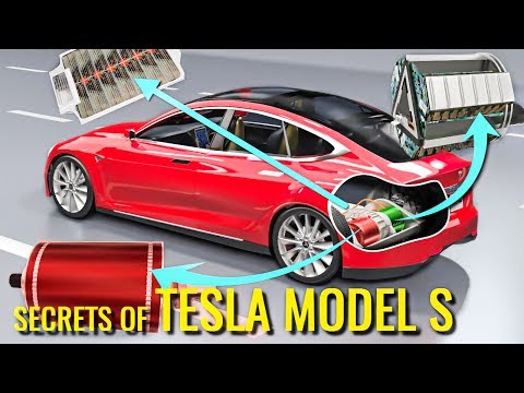
Understanding the Tesla Model S Power Electronic Components

Показать описание
Join me on a journey through 74 feet (22.56 meters) of high voltage cable through 10 different power electronics components of a 2015 and later Tesla Model S AWD.
TIMELINE:
0:00 Start
0:10 Introduction
0:50 Model S cables and common components
1:16 MUST SEE Orange cable core and shielding
2:38 Common component 1 - The Charge Receptacle
4:00 The charging receptacle cable size (50 sq mm) compared to the Tesla Model 3 cable size (95 sq mm)
6:12 Common component 2 - The On-Board Charger Module (48A 11.52 kW)
7:48 Single Phase or three-phase power input ports
10:10 The Interlock circuit
11:50 See the internal parts and connections of the on-board charger
12:28 MUST SEE The AC power input path through the on-board charger
12:55 AC voltage needs to be boosted to ~400V
13:39 The DC power output path through the on-board charger
14:10 The DC power input path through the on-board charger
14:32 The DC contactors used when supercharging the battery
15:47 A Safety Warning that should have been at the start of the video
16:54 The DC output from the on-board charger
17:26 Common component 3 - The Rapid Splitter (Front Junction Box)
17:50 The connection to the high voltage battery through the rapid splitter
18:22 The function and internal connections of the Rapid splitter
22:20 The position of the Rapid Splitter in the vehicle under the rear seat
22:50 Common component 4 - The rear motor inverter
24:54 Summary of the high voltage components in the rear of the vehicle
25:48 MUST SEE Pyrofuse Pack battery cable tag and pyrotechnic fuse
26:22 The standard 1300 amp fuse
26:40 The 2000 amp pyrotechnic fuse and its internal components
30:30 Why the battery fuse is needed
31:45 The high voltage components and cables at the rear of the vehicle
32:28 Common component 5 - The High Power Distribution Module (HPDM) (Front junction block)
33:20 See the four internal fuses and circuit board inside the HPDM
34:22 Another Interlock switch
34:48 The battery coolant heater control circuit
35:48 The high voltage connections from the Rapid Splitter to the HPDM
36:49 Common component 6 - The front motor inverter
38:17 The NVH Mat covering the front Drive Unit and motor
39:55 Common component 7 - The electric air-conditioning compressor (40A Fuse)
41:23 Common component 8 - The 2500 Watt DC to DC converter (30 A Fuse)
42:05 DC to DC converter output of 178 amps at 14 volts
43:03 the DC to DC converter charges the 12V battery
44:16 Common component 9 - The high voltage battery coolant heater (30 A Fuse controlled)
46:18 Common component 10 - The Positive Temperature Coefficient (PTC) Cabin Air Heater (40A Fuse)
48:18 The high voltage components and cables at the front of the vehicle
49:29 Almost all Electric Vehicles (EV) have the same common components shown in this video
50:39 Additional EV training is available for you.
51:12 Wrap up and summary
ABOUT US
ADDITIONAL TRAINING FOR YOU
DONATE TO OUR DEPARTMENT
 0:46:32
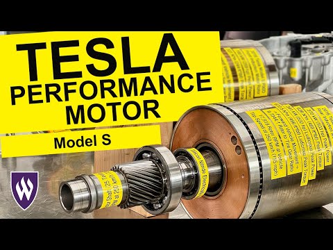
Understanding the Tesla Model S Performance Motor
 0:52:51
Understanding the Tesla Model S Power Electronic Components
 0:46:28
Understanding the Tesla Model S Front Motor
 0:31:39
Used Tesla Model S Ultimate Buyers Guide - Problems / History / Options explained.
 0:04:55
How the Tesla Model S is Made | Tesla Motors Part 1 (WIRED)
 0:27:50
Tesla Model S - Official Walkthrough HD
 0:11:37
Tesla Model S in-depth - Carbuyer
 0:12:08
Tesla Model 3's motor - The Brilliant Engineering behind it
 0:00:54
2024 Tesla Model S: My First Impressions Revealed
 0:10:09
Tesla Model S used buyer’s guide & review - It was a pioneer but is it good used? / Electrifying...
 0:10:24
How does an Electric Car work ? | Tesla Model S
 0:13:55
2021 Tesla Model S in-depth review – has it had its day? | What Car?
 0:10:34
9 Things to know for NEW Tesla owners
 0:17:41
Tesla Model S Plaid review - what will it do 0-60mph?
 0:14:23
2019 Tesla Model S - Review & Road Test
 0:13:17
Every Tesla Made! Model Y review
 0:07:25
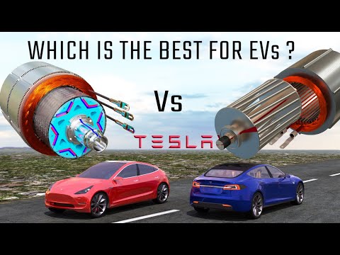
Model 3 Vs Model S Motor
 0:00:16
Tesla Model S Crash Test
 0:16:42
I Finally Drive A Tesla! Model S P100D
 0:11:20
Tesla Model S P100D Ludicrous Plus 2018 in-depth review | Mat Watson Reviews
 0:32:57
Nicht so schnell wie gedacht!: Tesla Model S Plaid – Bloch erklärt #173 I auto motor und sport
 0:06:52
Tesla Plaid Rear Drive Unit - Quick Look
 0:23:42
2018 Tesla Model S – The Original EV Game Changer
 0:13:25
18 VOICE COMMANDS FOR YOUR TESLA YOU NEED TO KNOW (Model S, Model 3, Model X, Model Y)
Комментарии