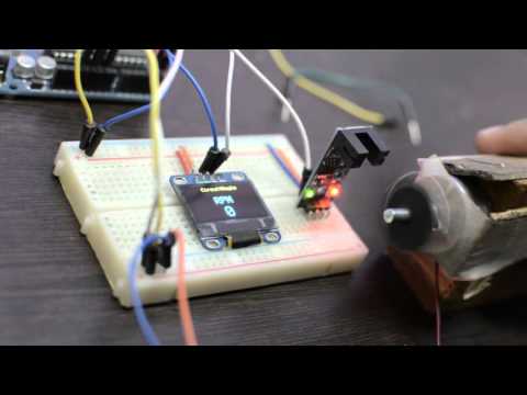
Arduino Uno Tachometer RPM using 3144 Hall Effect Sensor

preview_player
Показать описание
Here we look at the 3144 hall effect sensor and how it can be used to make a simple tachometer with the Arduino Uno and a 1602 LCD display

A copy of the code and a schematic diagram for this project are included in the shared folder here

Files contained are -
Schematic_Simple_Tacho....pdf - a pdf of the circuit diagram
Рекомендации по теме
Комментарии
Автор

One of the most useful, interesting, and straightforward video. A hidden gem 💎

wdwhitmer
Автор

Thanks for this - needed exactly this to test the RPMs on a bunch of brushless motors and this is simpler and more stable than an IR sensor👍

AusMarineRobotics
Автор

Thanks. Just used this in combination with a switec micro-stepper motor wired directly to 4 of the other pins so the same Arduino Nano now also drives a dial pointer on an antique RPM gauge for a hot rod. Whole assembly contained inside the original gauge housing, just plug in a USB lead for power from a phone power bank and can also use it for debugging. Really neat.

XenonJohnD
Автор

Awesome explanation of this particular hall effect sensor. This should get me up and running on a lathe I'm converting to CNC. ***EDIT*** It worked perfectly. I have one of these sending 1 pulse per revolution on my lathes spindle to LinuxCNC as my index phase since my encoder is mounted 3:1 gear ratio with pullies due to size constraints and not being able to fit another pulley the size of the spindle inside the cover. This resulted in the index pulse being sent 3 times per rev, which can't be corrected in the LinuxCNC HAL file. This worked out so perfect. Thanks for the clear details on everything.

Nordic_Goon
Автор

You really did a good job on this video. If you'd like, I can give you some code that uses the input capture feature of the Arduino. This ability, takes snapshots of the timer register, every time the pin gets a pulse. In the ISR, it only copies the timer value to a circular queue, after calculating the difference from the last pulse value. This means the queue contains period timings, in microseconds usually, but you can get to about 125nS resolution, iirc. At main level, you just pull entries from the queue at your leisure (reasonably, the queue is only so big). The mathematical inverse of the period time is revs per second, just multiply by 60 to get RPM. These measurements are sub microsecond and perfectly measured by hardware, even if you're in the middle of another ISR, it still takes the snapshot right when the pulse edge occurs. Its a great feature of the atmega chips (and others), but the Arduino framework doesn't use it, because it precludes the use of a couple of PWM pins. If you can live with that, its the absolute best way to take precision measurements of pulse timings. Input Capture is the way to fast RPM updates and precision accuracy. Theres a little more to it, like it uses pin 9 for the input pulse pin, you cant change that. Timer overflows occur every 32mS, so that's handled by another ISR for really long pulses. The capture ISR factors in the rollovers when it's calculating the time interval since the last pulse interrupt. I wrote the code about 15 years ago, so ill have to dig up a copy. Its not much, just some register manipulation in setup() and some in the interrupt handlers, but its really small code and lets you capture pulses as short as 15-20uS, yes microseconds, not millis. delay() and millis() are okay for many things, but precision isn't one of them.

Edit: I'd really like to see this method documented in a YouTube video, but I'm not gonna make one. 😊 I did it for some guy on the Arduino forum wayyy back. People rarely suggest it, though it's the most accurate way, and very little coverage of using it on Arduino exists on YouTube, that I know of anyway. I first did this with a pic chip about 20 years ago, to time mechanical clocks and watches. I wanted serious accuracy, and this is how you get that. I would be more than willing to talk to you about it further, if you're interested. For all I know you already know all this, but wanted to keep it simple, and I'm making a complete fool of myself. ;-)

tonyfremont
Автор

Thanks a ton for this video. The LED indicator trick helped me determine 2 of the 3 Hall sensors in my 13kw PMAC motor's Encoder circuit were bad.

charlesgunzelman
Автор

Hay Bruno! Thank you for actually explaining the code. You made a light come on as to using interrupts that I've been struggling with.

Thanks, 000, 000 for helping me understand Arduino code better.

- k -

cmccabe
Автор

la mejor explicacion que encontre, ademas fue entretenido y con ejemplos reales

melodicachan
Автор

From a hundred code i found, only from you that can work. Thanks a lot 🙏🙏🙏🙏

inside.rama_adis
Автор

Thank you for helping me understand, i am working on arduino with some sensors. But i got stuck in codes logic, your explanation help me understand everything.
Lol
Now i feel that have information sensor in my mind that illuminate with your video.

akikhan
Автор

What a lovely video. I subscribed and looked for any other video's because you are really entertaining and creative. And then I noticed you only uploaded three video's. I am sure people, including me, would really like to see more of your type of content. Cheers mate 👍

rolandberendonck
Автор

Great video! Simplest explanation of this use case.

christopherlarson
Автор

I like your dedicated bread board LED with built in resistor and jumper lead extensions. I have not seen that yet. I will definitely be making one. Thank You. You get a Thumbs Up and a Sub for that!! 😁

jlucasound
Автор

Thanks for the tutorial, helped with my application, I was a little concerned when you fired off the mower with you foot partially under it though.

striper
Автор

Very nice! Very detailed and explained tutorial, easy to understand! Thank u

zezeA
Автор

Wonderful video. We'll done. Great application of HALL sensor

BETA
Автор

This was very useful. Ive been trying to find out a way to convert one complete rotation of my stationary bikes wheel into 1 mouse click and this seems like a great way to do it.

AvrCdavr
Автор

I want to use a similar setup for a Arduino based RC car. Great video

occrc
Автор

Nice video, thanks for sharing.

I was looking how those sensors are used to detect speed and your video showed it nicely. In the future, I would like to modify some organ pedals I have and somehow measure the speed that the person operating them uses to touch the pedals. This is translated as the volume of the note.

jmemusic
Автор

Very nice video. It could have been a lot more exciting though... just after you started the lawn mower with your foot under it!

johntoe