filmov
tv
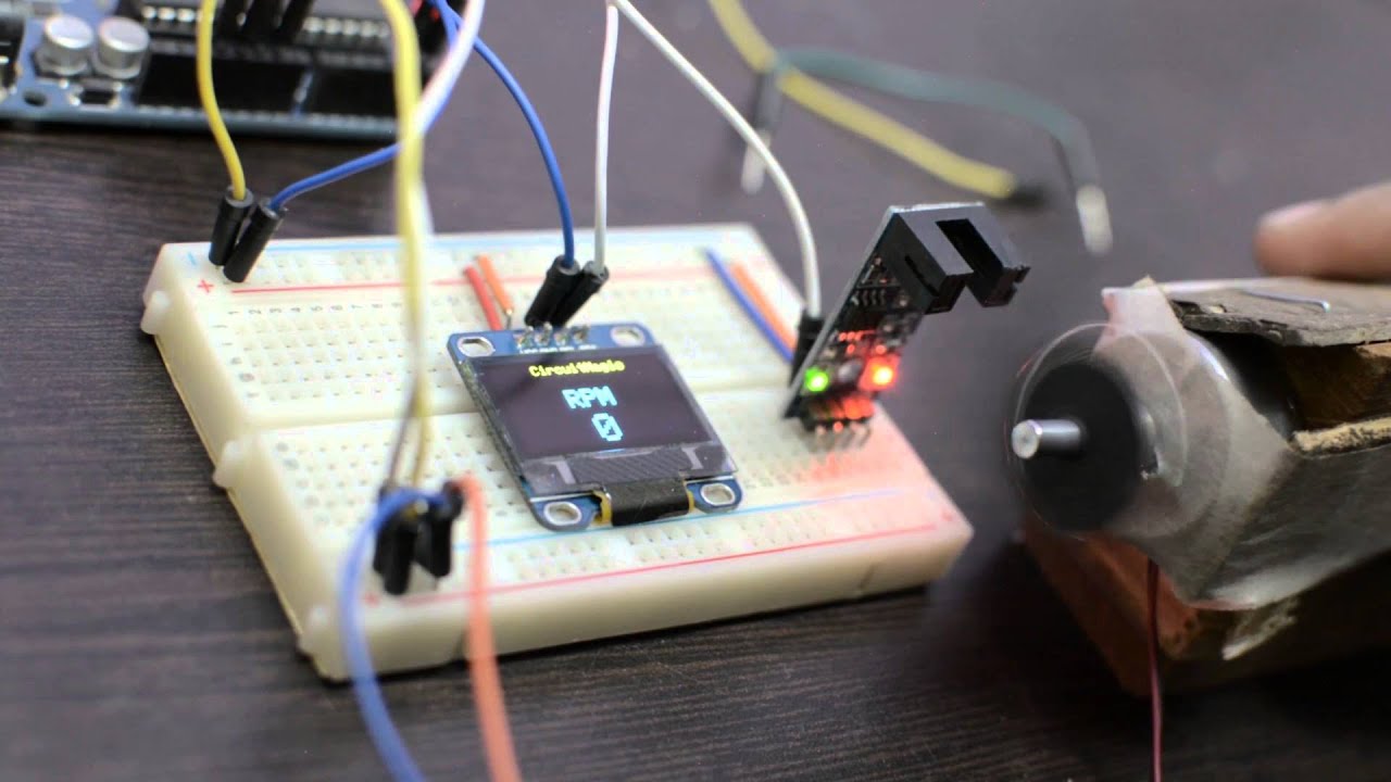
DIY RPM Tachometer with Arduino | RPM Counter |
Показать описание
This video will teach you how to make RPM Tachometer, which helps you to check the speed of any motor.
For making this you required an Arduino, OLED Display, Optical sensor, Breadboard and few jumper wire which are very easily available in the market.
For more information please visit the project page where you can get the circuit diagram and program code for Arduino.
If you like the video Please don't forget to like and comment and subscribe to my YouTube channel.
 0:02:22
DIY RPM Tachometer with Arduino | RPM Counter |
 0:06:31
Tachometer Project on Makerfabs MaTouch 1.9
 0:10:48
Tachometer (RPM Meter) || DIY or Buy || How a 3€ sensor outdoes a 29€ product!
 0:03:54
Arduino Tutorial: Tachometer (RPM Counter)
 0:14:12
Arduino Tachometer (RPM meter) with IR sensor module
 0:04:50
How to make a DIY RPM Meter ( Tachometer) with Arduino
 0:02:06
DIY Digital Arduino Tachometer | RPM Counter Using Proximity Sensor (IR)
 0:00:48
Arduino led tachometer and shift-light v 0.1
 0:12:19
Homemade Distance, Angle, Level and RPM meter
 0:01:17
Nextion Project - Tachometer for KTM
 0:03:11
Tachometer (RPM-meter) with IR proximity sensor & Arduino - Drehzahlmesser mit IR-Sensor und Ard...
 0:06:16
How to make Arduino Digital Tachometer | RPM Counter| PROKNOW
 0:10:11
DIY ARDUINO RPM REV TACHO SIM HUB DASH
 0:00:28
Arduino RPM counter or tachometer
 0:13:36
How to Make Tachometer using Arduino | RPM Meter with PNP and NPN Sensor
 0:13:59
Arduino Uno Tachometer RPM using 3144 Hall Effect Sensor
 0:02:40
How to make RPM Tachometer using LM393 IR speed sensor
 0:08:25
How to use Optocoupler sensor module as RPM meter (Tachometer)
 0:00:38
Honda cb550 arduino tachometer
 0:01:55
Arduino Car Cluster with OLED Display (Dashboard, gauges, controls, SSD1306, u8glib)
 0:13:10
RPM meter with arduino DIY (IR sensor and 3D printed case)
 0:03:14
How to make TachoMeter using Arduino Uno and IR sensor | Tachometer | Arduino Projects #diy
 0:01:00
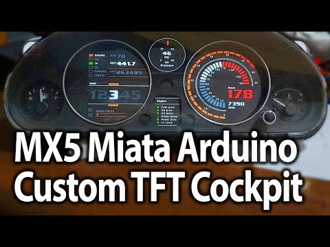
Digital Dash MX5 Miata Arduino Custom TFT Cockpit
 0:01:28
DIY Tachometer / RPM Meter
Комментарии