filmov
tv
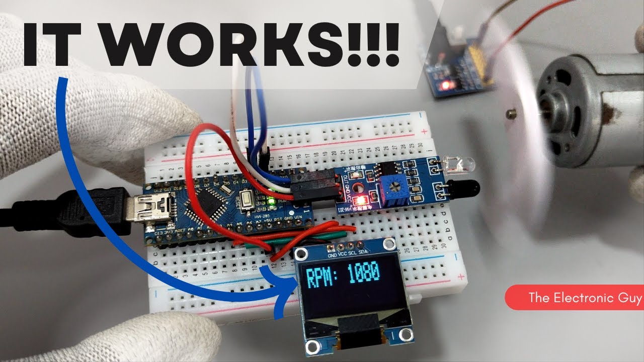
I made this Tachometer using IR sensor!
Показать описание
Circuit diagram and code:
Steps to make this tachometer:
1. Put the Arduino Nano on the breadboard
2. Connect the SDA and SCL pins of OLED to A4 and A5 respectively.
3. Connect the OUT pin of the IR sensor to digital pin 2 of Arduino Nano and give +5v and GND connections.
4. Upload the code. (The code is pinned in the first comment.)
Explanation:
The current time in milliseconds is stored in the 'currentMillis' variable.
If the time difference between the current time and the previous time stored in previousMillis is equal to or greater than 1000 milliseconds (1 second):
The interrupt is temporarily detached to avoid conflicting with the counter variable.
The RPM value is calculated by dividing the counter value by 2 (assuming each revolution triggers two interrupts) and multiplying it by 60 to convert it to RPM.
The counter is reset to 0.
The interrupt is reattached to the IR sensor pin.
The previousMillis is updated to the current time.
The OLED display is cleared.
The RPM value is displayed on the OLED display.
 0:02:04
I made this Tachometer using IR sensor!
 0:10:48
Tachometer (RPM Meter) || DIY or Buy || How a 3€ sensor outdoes a 29€ product!
 0:07:05
HOW TO MAKE TACHOMETER USING ARDUINO
 0:02:06
DIY Digital Arduino Tachometer | RPM Counter Using Proximity Sensor (IR)
 0:03:54
Arduino Tutorial: Tachometer (RPM Counter)
 0:06:16
How to make Arduino Digital Tachometer | RPM Counter| PROKNOW
 0:07:00
DIY: Turn a Volt Meter Into a Tachometer
 0:02:40
How to make RPM Tachometer using LM393 IR speed sensor
 0:02:03
DIY digital tachometer (RPM meter) using arduino
 0:02:21
How to build a simple laser tachometer
 0:08:42
How to make RPM meter | Digital Tachometer using IR Sensor
 0:04:22
How To Make Digital Tachometer
 0:08:45
How to make tachometer using arduino
 0:03:14
How to make TachoMeter using Arduino Uno and IR sensor | Tachometer | Arduino Projects #diy
 0:00:19
Arduino Tachometer with Magnetic Hall Sensor
 0:18:04
Tachometer for a lathe or mill.
 0:00:48
Tachometer APP that really works! | For Android and IOS
 0:00:35
digital rpm meter connection with proximity sensor || tachometer connection #proximitysensor #rpm
 0:01:34
Learn How to Make Arduino based Digital Hand-Held Tachometer Using IR Sensor | DIY Projects
 0:13:59
Arduino Uno Tachometer RPM using 3144 Hall Effect Sensor
 0:01:28
DIY Tachometer / RPM Meter
 0:02:22
DIY RPM Tachometer with Arduino | RPM Counter |
 0:03:57
Simple Tachometer/ RPM counter using proximity sensor
 0:14:12
Arduino Tachometer (RPM meter) with IR sensor module
Комментарии