filmov
tv
Arduino PID Control System (Ball and Beam)

Показать описание
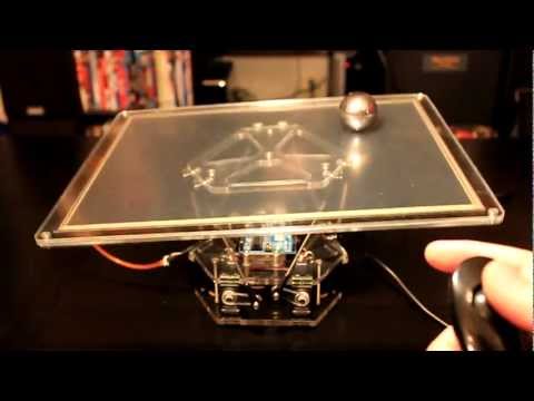
This is a ball-and-beam control system I designed and 3D printed to learn about PID control.
I've posted the CAD and code for this project on my Github page here:
The control electronics consist of an Arduino Uno, a CNC shield, and a TMC2209 stepper motor driver. The TMC2209 motor driver allows the stepper motor to operate very quietly by interpolating step signals into 1/256 microstepping.
The distance sensor I used is an HC-SR04 ultrasonic distance sensor. This sensor typically provides rather noisy data, so I used a moving average to act as a low-pass filter and attenuate the high frequencies. I also added some simple outlier rejection to remove the occasional erroneous measurement.
I used a 12-bit AS5600 absolute magnetic encoder on the stepper motor to track the position of the motor. These sensors operate on the Hall effect and use I2C protocol to communicate with microcontrollers. I designed and printed a housing that attaches to the back of a NEMA-17 stepper motor and holds the encoder board in the correct location relative to the magnet. The encoder magnet is diametrically magnetized and is attached to the back of the motor shaft.
I originally planned to use a ping pong ball as the rolling element of the system, but the distance sensor was not able to reliably provide clean data. I think the reflected sound from the sphere was too small in this case. That's why I made the cart with a large acoustically reflective surface.
To set the PID target position, I mapped the output of a 10k potentiometer to the position along the beam.
 0:00:19
Balancer - plate balancing a ball with PID controller, resistive panel and servos, arduino
 0:12:35
Ball balance project with Arduino PID controller system | Arduino PID controller project
 0:13:13
PID Balance+Ball | full explanation & tuning
 0:00:38
Arduino PID Balancing of a Ball on Beam + code
 0:00:20
Arduino PID controlled Ball on Beam balance
 0:00:22
Ball and Beam balance
 0:06:19
DIY Arduino Ball and Beam : PID control
 0:02:35
Arduino PID Control System (Ball and Beam)
 0:04:23
Arduino Project - Ball Levitation using PID controller
 0:01:05
Self-Balancing Ball Control System Project | PID Control
 0:29:51
Arduino PID Controller - From Scratch!
 0:00:54
BALANCING A BALL ON BEAM WITH PID USING ARDUINO AND PLOTTING GRAPH IN MATLAB
 0:05:26
Ball and Plate Arduino PID control
 0:15:27
Simple Experimental Tuning of PID Controllers using Arduino and Ball and Beam System
 0:00:14
1D Arduino Ball Balance
 0:00:51
Arduino ball and beam balancing using PID controller
 0:02:23
You Can NOT Drop The Ball! Watch Now The Crazy Magic of PID Controller (Arduino inside)! DIY Project
 0:00:24
ENGR435L - Ball Balance with PID Control
 0:05:18
BALL AND BEAM using Arduino PID Control
 0:08:55
I Built a Ball Balancing Robot
 0:18:45
Arduino PID Controller - Demo with Source Code!
 0:02:03
Ball Balancing PID System
 0:00:44
Ball & Beam - PID Controller - Arduino and Matlab
 0:03:32
Ball and Plate PID control with 6 DOF Stewart platform
Комментарии