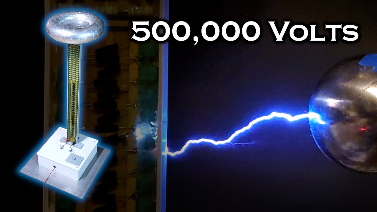
500,000 Volt Lightning Tower

preview_player
Показать описание
In this video I'll show how i use a diode-capacitor chain to boost 9,000 volts AC to over 500,000 volts DC. This is known as a "Cockroft-Walton" type generator, and was used to generate high energy discharges for early particle accelerators.

It looks very similar to a Tesla coil, but it's sort of the exact opposite, because it outputs DC instead of AC. This gives it a unique capability that a Tesla coil doesn't have - it can produce static electricity. In fact, at 500kV, some objects can be given enough static charge to repel each other like magnets. It'll pull your hair toward it from across the room - similar to a Van de Graaf generator, but much more powerful.

The input to the multiplier is 9,000 volts peak at around 50 kHz from a flyback transformer i wound myself being driven by a ZVS driver with a 24-volt supply from a 6S LiPo battery. I've covered the ZVS driver in several of my other videos, so I didn't bother to do so in this one.

If you're thinking of recreating this project, just keep in mind that a discharge from this device is far more dangerous than an arc from a Tesla coil. The current from a Tesla coil will travel along the outer surface of your skin because of the high frequency AC - usually in the hundreds of kHz. The DC discharge from this multiplier will go straight through your body. Always make sure to use a long, non-conductive (DO NOT use wood!!) stick with a solid connection to ground when you're making arcs, and when you're finished, keep the electrodes shorted together for a minute or so to ensure any residual charge has bled off.

Capacitors and diodes are just cheap units off of amazon:

20 kV / 100 mA diodes:

20 kV / 1 nF capacitors

Music Used:

Kevin MacLeod - Lobby Time
Kevin MacLeod - Hard Boiled
Kevin MacLeod - Groove Groove
Рекомендации по теме
Комментарии
Автор

Thanks, i now have an explanation for the thunder that happened 3 minutes after you posted this video.

thekuba
Автор

Oh the memories.
As a teenager in the 1960s, I took the 12K volt neon sign transformer from my Tesla coil and constructed a six stage voltage multiplier. I used TV diode tubes with attached battery for isolated cathode heater. I used TV high voltage capacitors. The meter-high frame was wood and my attempt at eight stages failed when the arc crawled down the frame to ground. I too now recall the electrostatic effects, the buzzing, hissing and the smell of ozone. My spark-gap Tesla coil pulled 20 inch (50 cm) AC arcs when tuned, and the voltage multiplier pulled 8 inch (20 cm) DC arcs by comparison.

Magnificent.

stephenlreed
Автор

Seeing all the plastic parts you fabricated to build this project makes me realize how much I want a 3D printer. Great job and safety sense.

stevetalin
Автор

I just finished building a full wave multiplier stack. I used 10 nF, 20kV caps with the 2CL2FM diodes. The old tap water resistor works great on extremely high voltages. I put 5 kV input @ 50 khz / 50 mA and I'm getting 120 kV on a 12-stage CW multiplier. On 10 kV input, I'm running 240 kV + output on the multiplier. Having larger capacitors on the multiplier and doubling up diodes (2 x 2CL2FM diodes in series) helps with voltage stand-off protection. Mineral oil is the best dielectric for the multiplier.

Your diode multiplier uses a huge number of stages. So in reality you are likely dropping voltage. Raising the capacitance might help reduce voltage losses.

jordanwhyte
Автор

Thanks so much for making this great video tutorial! I have actually been looking for relatively easy ways to create DC voltages in the MV range, but I could not find any good tutorials. Up to now.

HuygensOptics
Автор

Truly some of the best EE content YouTube has to offer! Great job!

frzer
Автор

Just a quick one, (basically) all epoxies shrink when they cure so a really long casting like that will bend as it cures regardless of heat. If you can balance the support in the middle rather than on one side it'll shrink square at least. The more filler you have in the epoxy the less it'll shrink if that helps.
Also yeah large lumps of epoxy will exotherm pretty hot. I've seen them catch fire in the past lol. So yes a slow cure is a good idea too.

For version two perhaps look into a borosilicate glass tube for the tower, they are relativley cheap in 80-100mm diameter sizes and have pretty decent dieletric properties. Though I'm not sure how well pretty decent stands up to a million volts.

zyeborm
Автор

As you noticed, corona discharge was a huge problem with your multiplier stack. In scientific and commercial multipliers, this is greatly mitigated by smoothing the electric field to reduce the gradient, in much the same way that the topload allows you to collect charge. I've built multipliers in the 30-50kV range, so take my advice with a grain of salt, though I have had plenty of flash-over fun.

First, all of your solder joints are sharp points. It really doesn't matter what your dielectric is (including vacuum!) when those points generate extreme voltage gradients. Everything will very quickly break down in that environment. When going for extreme voltages, the easiest way to ease these gradients is to bury your solder joints in some flavor of small sphere. Conductivity isn't important so iron, steel, brass, and other inexpensive metals work fine. Beads, ball bearings, whatever you can find that is inexpensive should work.

The more extreme way of dealing with this is called a corona-ring. This is where you attach each stage of your multiplier to a high aspect ratio toroid that wraps all the way around your multiplier. This makes the electric field gradient from ground to top-load voltage very smooth, and since your diodes and capacitors are sitting inside this field, there is a much lower potential (haha) for any sharp solder joints to emit corona. If you go this direction, take a cue from those isolators you see on high voltage power lines and make rings on a stick to increase creepage distance when you build supports for the corona rings.

Second, increase your drive voltage and reduce your stage count. CW Multipliers have a complex capacitive reactance that gets higher as the number of stages go up, so your output droop can get bad as stages are added. In my case I went from a 6 stage monopolar design to a 3+3 stage bi-polar design and saw a significant reduction in output voltage droop with the same output load, so my real power throughput also went up. Additionally, the style of multiplier you used was a half-wave rectifier and converting to a full wave rectifier multiplier can help with voltage droop as well. I was using some parallel capacitors in my multiplier and switching them to a full-wave rectifier also significantly reduced droop at the output. This does require a center-tapped transformer, so you may find the complexity not worth the trouble.

Finally, in a ZVS driver, the transformer drive voltage is about 3.2 times the input voltage, which is why your transformer output significantly more voltage than you expected. In fact, you said you drove it at 8V, about exactly right to get the output voltage you wanted. Probe the tank capacitor voltage and you will see the problem!

SRFirefox
Автор

I am perfectly satisfied to watch you take all the risks my brother!

SomeGuyInSandy
Автор

I find this video very interesting. Instead of searching for a flyback, next time search for a horizontal output transformer. In the days of tubes the rectification was by a tube like a 1BG3T. Thanks for your content!

jerryvitale
Автор

You deserve to turn on ad's, weather you "need" them or not! Love this content and hope you continue to keep it up! Thank you so much Mr Hyperspace Pirate!

Hookmodo
Автор

Thanks for uploading this video. It shows process of learning by trial and error. It must be dissapointing to get only 50-60 kV output while striving for 500 kV

imeprezime
Автор

Electricity is so beautiful isn't it? On one hand, corona discharge can be your worst nightmare and ruin your project. On the other, you can take advantage of it and make a motor spin. Fascinating

CLUBKILLE
Автор

very good, I made one like it two years ago but instead of epoxy I used paraffin wax and put it in a PVC pipe and there is no leaks.
I recorded the process in case you want to take a look

gabrielhacecosas
Автор

Nice CW voltage multiplier. I have a few suggestions based on personal experience. Use mineral oil instead of epoxy. Even though its messy you can repair things when they break or make modifications. Its also less likely to trap air. Use a separate resistive load. This allows much more flexibility in the selection of load resistance and also makes the height of the multiplier lower. Don't implement more than about 15 stages. Efficiency drops off rapidly above that number. Use a higher drive voltage instead even though this makes the design of the HV power supply more complex. You can look at the 14-stage CW voltage multiplier on my channel for ideas if you wish.

I used 2 COTS AC flyback transformers connected in parallel for additional drive current. A COTS ZVS driver was used to drive the flybacks with a drive frequency of 28 Khz. This combination yields 15 KV peak AC to drive my multiplier stack. I could post a link with even more detail but YT will delete my comment.

littleshopofelectrons
Автор

Wow, very impressive construction Mr. HP!

MiniLuv-
Автор

You might consider making your multiplier into several modules. This way, in case one diode or capacitor fails, you dont lose the entire chain.

weirdsciencetv
Автор

That tripping hazard joke was underrated 😂

ChrisTheHoosier
Автор

Nice video as always! Always interested in electrostatic/ion wind effects that are new, especially if you can get enough wind flow to make a truly bladeless fan instead of by using an impeller. 😁

curiousviewer
Автор

I love your content! Thank you for sharing your amazing projects. I wish I knew even half of what you do.

jayduffy