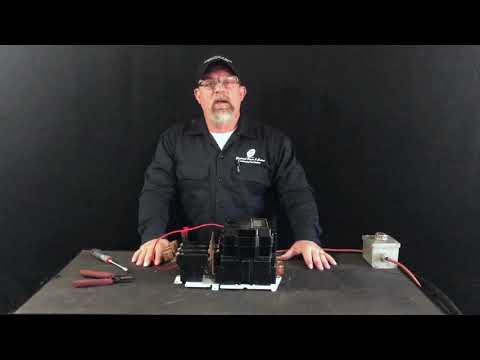
Bench Test a 3 Wire Crankshaft Position Sensor

preview_player
Показать описание
In this video I tackle how to bench test a 3 wire crankshaft position sensor. This would probably work for any hall effect sensor as well. This came out of my 98 Ram 1500, thought the principal should work for many of the 3 wire sensors. Make sure to check your manual and double check the wiring diagrams I have in the video to make sure you're doing it right. I hope this helped, because I could not for the life of me figure out how to test this on a bench and not on a vehicle.

Timestamps:
0:00 - Intro
1:15 - What you need
3:11 - Wiring diagrams
4:09 - Testing

I hope you enjoyed watching this video. If you have any feedback or additional info, I'd love to hear from you. I try to always make quality content that I would like to see myself.
_________
|\.........../ |
|..\ ......./..|
| FUMAR |
|...../..\.....|
|__/___\__|
Рекомендации по теме
Комментарии
Автор

Really hope this helps some people out. Hadn't seen anything like this yet on youtube, so wanted to help fellow car people out.

NFumar
Автор

Good afternoon I was checking your video and I did a bench test to a crankshaft sensor Hall effect (3 cables) but I supplied 5V with a topdiag 200 tool, other cable to ground and the other to a multimeter to see the voltage flow but the voltage went from 1v to 0 when you approached an iron piece as you do In video, in this case why I have to use a resistance? Can you explain to me thanks

eduardoenriquebarreto
Автор

First let me thank you for this very useful video, just what l was looking for ref three pin bench test.
The 10k resistor between 5v supply and signal imput is news to me l never knew this was required.
This must be the reason why my previousr bench tests have failed, as this has never been included in my test kit hook up.
Are resistors one directional or can they be fitted either way round?

colin
Автор

Appreciate the video and thought this would allow me to test my 3 wire from a 2001 dodge Cummins. I bouught a new camshaft position sensor and hooked it up exactly as you had showed checked and rechecked several time t omake sure the connections were correct. Under these conditions bringing a metal object to the surface of the sensor would not trigger the switch and bring the voltage down - no change. However with the same sensor hooked to the wiring harness of the truck it switches exactly as describes with the metal object. Is this something current related do I need a resistor or more resistors of other sizes beside the 10K? Any insight appreciated.

fendercare
Автор

A 2005 Mitsubishi l200 with an inline 4 COP ignition system with an engine code of 4G64 SOHC engine installed in it was pretty okay. Thus, the client used it for some errands from the morning hours to the afternoon and it was perfectly running. Nevertheless, when the client returned home the 3rd time, his boy reversed the vehicle within the man's compound for a wash. If I'm not mistaken though, the car stalled on him or it was about 20 minutes ago when the boss was about to move again with the car that the noticed the problem. But they said it was only a reverse he did.
The car would crank, start but stall immediately within 4 seconds. I was called to rectify and fix the issue.
One of the things I checked when the car was cranked was the fuel system. With ignition on, the car wouldn't pump even an iota of fuel through the fuel hose to the engine.
Bypassing the pump directly to the battery positive and ignition switch to the on position, there's a great pressure or amount of fuel from the fuel hose. Alternatively, I unplugged and plugged back the 3 wire CKP sensor connector and noticed a great buzz of fuel too. I proceed with testing fuses and relay from the engine bay and only one fuse was bad and it was replaced. From inside the car I all relays and noticed that the CKP sensor no longer pumps fuel to the engine with the unplugged and plugged method but the bypass method and noticed the relay location that controls the CKP fuel pressure buzz on ignition to the battery positive still wasn't affected. I didn't know more to do there than swap the relay.
Next, I checked for injector pulse and noticed only a single or no pulse at all.
I tried to hook up a scanner to conduct some test however, the scanner was not connecting.
Next, I checked and observed that the timing was pretty weak. I showed the client, he said I should replace it which I did.
Presently, it's a crank no start, single injector pulse no spark, no communication to my scanner.
Please, how can I address this issues? How can I bench test the car 3 wire CMP, CKP sensor with a multimeter or a test light or LED light outside the car? Where is the fuel pump relay location. Please send me the car wiring too, partaining to the no start most likely.

davidessien
Автор

How about a 4 wire crankshaft position sensor. For a 92 Ford ranger 2.3l lima engine 5 speed trans? Can't find a diagnosis video for that.

johnnybrown
Автор

I get 5v off my signal wire but the sensor does not react to anything metal at all, just a constant 5v (bmw n43) will update when new sensor comes later.

SomeHappyTeddys
Автор

Thanks for the procedure. But the crank in a car turns faster than you probe and so I wonder if the sensor may look fine with a slow test but not work well at a faster pace as required by the ECM. Perhaps a frequency setting on a multimeter may be a better test. Mine fails to show 5V randomly when away from metal.. (as if it gets stuck) but seems to start working again after a few tries.

CarlosGonzalez-hzum
Автор

It’s in the perfect spot for the vans. Guess you can’t please everyone

riverflyswatter
Автор

I have a ram 1500 ecodiesel 3.0. i can not get a digital output from the 3 "new" store bought ckp that i have ordered. do u know if there is some diff. test between 3 wire sensers?

paulme
Автор

honesrly it would be ezer to see your wiring insted of the diagram can you make onother video?

JuanGutierrez-hgjc
welcome to shbcf.ru