filmov
tv
Pure Electronics Repair 3 Learn Methodical Fault Finding Techniques / Methods To Fix Almost Anything

Показать описание
LER #304 This time I was asked to repair the control PCB from a large clock tower on a commercial building in the UK! Obviously I know nothing about clock towers and how they work but I do know some stuff about electronics... so of course I accepted the job. I mean, how hard can this be? It's all electronics at the end of the day. Yeah?
I work in collaboration with:
The Electronics Channel (with Carlos and Detlef)
Gran Canaria Uncovered
For All Your PCB needs: free $5 discount coupon
Equipment used in my videos. These are affiliate links, you pay the normal price and I make a small commission.
TEST METERS
Aneng AN8009
KM601
VC480C+
MESR-100 ESR METER
XC6013L CAPACITOR METER
TM-902C TEMPERATURE METER
FNB58 USB ANALYZER
PCI POST ANALYZER
TL460S Plus PCI_E ANALYZER
MULTIMETER PROBE KIT KET05
OSCILLOSCOPES
FNIRSI 1014D
FNIRSI DSO-TC3
FNIRSI DPOX180H
BENCH PSU
NPS3010W
SOLDERING
T12 Station with M8 9501 Handle
SUGON T26D
QUICK 861DW
PROS'KIT SS-331H
THERMAL CAMERA
Infiray P2 Pro
MICROSCOPES
Amscope Optical Microscope (copy)
ANDONSTAR AD407
EEPROM Programming
TL866 II+
CH341A
If you would like to support this channel
You can send donations
You can subscribe to Patreon
You can click Join to become a channel member
Thank you
Richard
 0:59:38
Pure Electronics Repair 3 Learn Methodical Fault Finding Techniques / Methods To Fix Almost Anything
 0:42:16
Pure Electronics Repair. Learn Methodical Fault Finding Techniques / Methods To Fix Almost Anything
 0:02:24
profit Pure Electronics Repair 3 Learn Methodical Fault Finding Techniques / Methods To Fix Almost
 0:42:28
Use Basic Electronics Knowledge To Repair Industrial Electronics - Pure Methodical Fault Finding
 0:47:19
Pure Electronics Repair 2 Learn Methodical Fault Finding Techniques / Methods To Fix Almost Anything
 0:52:57
Pure Electronics Repair 2: Part 2 Learn Methodical Fault Finding Techniques To Fix Almost Anything
 0:40:02
Use Basic Electronics Knowledge To Repair Industrial Electronics - Pure Methodical Fault Finding Pt2
 1:59:13
Advanced diagnostic methods using pure electronics knowledge without schematic
 1:31:47
Pure Electronics Repair - A Live Session. Transmodulator Does Not Power Up, Can We Fix It?
 0:32:34
300B Pure Class A Single Ended Triode (SET) Monoblock Tube Amplifiers – Design, Build and Demo
 0:07:08
DR #51 - Pure Electronic Troubleshooting with an NAD 3240PE Stereo Amplifier
 0:19:55
#1099 How I learned electronics
 3:51:40
Power supply project - How to light a BBQ using pure electronics :P #Beginners diy projects
 0:15:33
TBE 300w pure sine. repair
 0:01:40
How To Make A CPU
 0:04:24
Pure Pleasure QDK11-D warm blanket
 0:12:46
PURE Evoke DAB Radios | No Display & No Power | REVISIT
 0:13:39
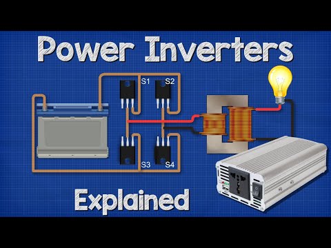
Power Inverters Explained - How do they work working principle IGBT
 0:00:58
How does a spectrophotometer work?
 0:00:26
Portable Battery Packs are lying to you… #shorts
 0:11:25
Recovering Pure Silver From Electronic Scrap With Amazing Technique
 0:07:17
What Is An Atom? | The Dr. Binocs Show | Best Learning Videos For Kids | Peekaboo Kidz
 0:00:44
Motorola G Pure's Unknown Unique Features 👑✨
 0:04:05
How to Extract Gold from a Circuit Board | Earth Science
Комментарии