filmov
tv
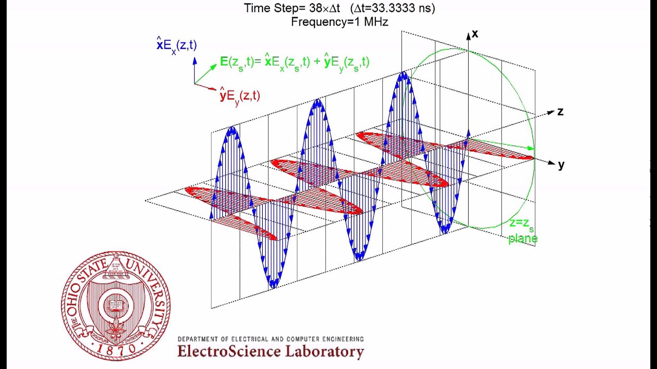
Right Hand Circular Polarization (RHCP) Animation
Показать описание
Uniform plane wave traveling in +z direction. x and y components of the electric field are shown as traveling, the total electric field at z=zs is shown in green.
The convention used is as defined in the IEEE standard (not the one used in many optics book)
To watch linear, circular and elliptical polarization animation in a single shot, see the below video:
Also see below:
Oblique Plane Wave Reflection From Half Space
Radiation from a Circularly Tapered Dielectric Waveguide
Right Hand Circular Polarization (RHCP) Animation
Linear Polarization Animation
Left Hand Elliptical Polarization (LHEP) Animation
Standing Wave Pattern (SWR) Animation
Electromagnetic Propagation of UWB Short Pulse in Random Medium
Dipole Antenna Radiation
 0:00:20
Right Hand Circular Polarization (RHCP) Animation
 0:07:14
Left vs Right Circular Polarization | WHICH IS BETTER (LHCP vs. RHCP)
 0:02:01
Circular Polarization — Lesson 7
 0:00:33
Linear, Circular and Elliptical Polarization Animation in a Single Shot
 0:02:14
Why do you need circularly polarized antenna for working amateur radio satellites?
 0:11:40
Both Types Of Circular Polarization? - Maple Wireless Mjolnir First Thoughts
 0:00:33
Left hand / Right hand Circular Polarization in CST
 0:03:30
Antenna Circular Polarization
 0:00:13
Righthand Circular Polarization
 0:08:59
Circular Polarization Numerical Example
 0:00:51
Is this antenna LHCP or RHCP?
 0:00:41
2.4GHz S shape dual circular polarization RHCP LHCP antenna on CST
 1:13:27
Undergrad Antennas Lab - Part 9 - Circular Polarization (CP)
 0:01:50
RFID Circularly Polarized RHCP LHCP Stacked Patch antenna in hfss
 0:02:07
Left hand / Right hand Circular Polarization in cst | result in cst
 0:01:24
Ku Band antenna in hfss Dual Circularly polarized RHCP LHCP
 0:00:41
(RHCP) (LHCP) circular polarization, axial ratio below 3, feed at angle 2.4GHz 4.8ghz using CST
 0:01:00
Right Handed and Left Handed Circular Polarization #gradplus #gatepreparation #electromagnetics
 0:00:35
axial ratio below 3, dual circular polarization (RHCP) (LHCP), diagonal slot 2.4GHz 4.8ghz using CST
 0:00:13
Circular Polarization animation by Russell Kightley
 0:00:33
axial ratio below 3, dual circular polarization (RHCP) (LHCP), diagonal slot 2.4GHz 4.8ghz using CST
 0:08:17
ELEC311 - Basic Wave Polarization - Circular Polarization
 0:00:13
Lefthand Circular Polarization
 0:01:19
What is Polarization of an Antenna?
Комментарии