filmov
tv
Linear, Circular and Elliptical Polarization Animation in a Single Shot

Показать описание
#polarization
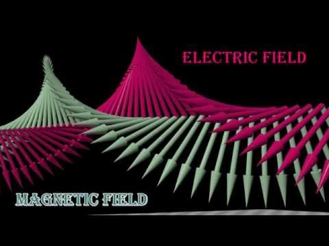
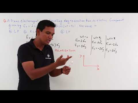
The time-domain progression of the total electric field components of plane waves traveling in the +z direction with various polarizations. Specifically, linear, right hand circular and elliptical polarizations are shown.
The convention used is as defined in the IEEE standard (not the one used in many optics book)
Also see below:
Oblique Plane Wave Reflection From Half Space
Radiation from a Circularly Tapered Dielectric Waveguide
Right Hand Circular Polarization (RHCP) Animation
Linear Polarization Animation
Left Hand Elliptical Polarization (LHEP) Animation
Standing Wave Pattern (SWR) Animation
Electromagnetic Propagation of UWB Short Pulse in Random Medium
Polarizzazione di una Onda ELM: Lineare, Circolare ed Ellittica.
 0:00:33
Linear, Circular and Elliptical Polarization Animation in a Single Shot
 0:17:59
Polarization - linear, Circular & Elliptical Polarization | Antenna Parameters | Engineering Fun...
 0:14:30
Polarization of light, linear and circular | Light waves | Physics | Khan Academy
 0:04:40
Circular Polarization
 0:19:50
Polarization of Light: circularly polarized, linearly polarized, unpolarized light.
 0:01:07
Elliptical Polarization — Lesson 8
 0:20:34
description of linear circular and elliptical polarization
 0:10:25
Electro Magnetics Theory - Polarization
 0:19:44
Antenna Part 7. Antenna Polarization. Linear (Vertical & Horizontal), Circular & Elliptic Po...
 0:19:15
Polarization of EM Waves (Linear, Circular and Elliptical Polarization)
 0:00:20
Linear Polarization Animation
 0:02:01
Circular Polarization — Lesson 7
 0:01:39
Linear Polarization — Lesson 6
 0:08:59
Circular Polarization Numerical Example
 0:01:08
Polarization of Electromagnetic Waves — Lesson 5
 0:10:50
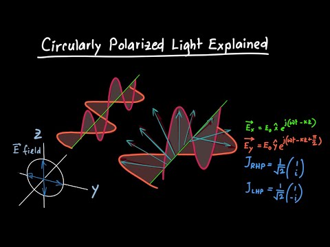
Circularly Polarized Light Explained
 0:30:48
PRODUCTION OF PLANE POLARIZED, CIRCULARLY POLARIZED AND ELLIPTICALLY POLARIZED LIGHT || WITH NOTES |
 0:25:34
ELECTROMAGNETIC THEORY: Description of Linear, Circular and Elliptical polarization
 0:09:49
Polarization || Linear, Circular & Eclipse Polarization || Graduation Physics topics
 0:14:23
Elliptical Polarization and examples on different Polarization
 0:02:49
Linear Circular and Elliptical Polarized Light
 0:00:20
Right Hand Circular Polarization (RHCP) Animation
 0:00:42
Linear, Circular and Elliptical Polarization Animation in a specific plane
 0:13:38
POLARIZATION AND TYPE OF POLARIZATION । Linear Circular and Elliptical Polarization। Hindi-English...
Комментарии