filmov
tv
In the figure a potential difference V = 100V is applied across a capacitor arrangement
Показать описание
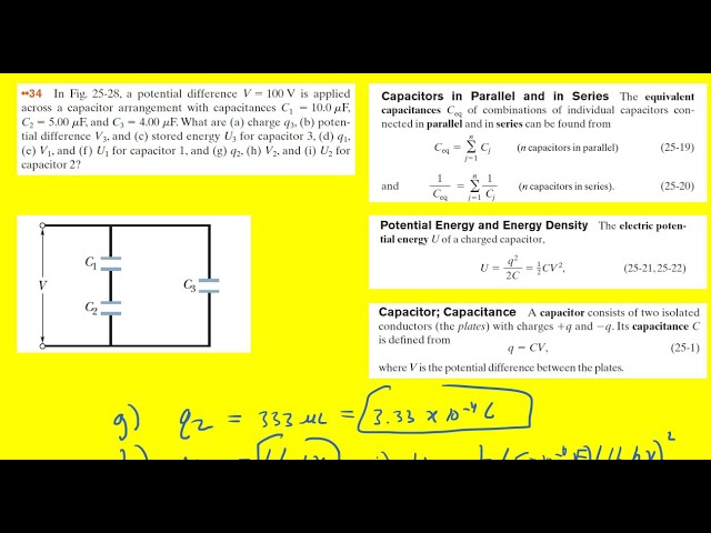
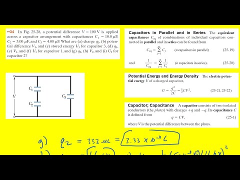
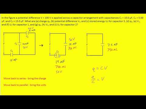
In the figure a potential difference V = 100 V is applied across a capacitor arrangement with capacitances C1 = 10.0 µF, C2 = 5.00 µF, and C3 = 4.00 µF. What are (a) charge q3, (b) potential difference V3, and (c) stored energy U3 for capacitor 3, (d) q1, (e) V1, and (f) U1 for capacitor 1, and (g) q2, (h) V2, and (i) U2 for capacitor 2?
 0:10:50
In the figure a potential difference V = 100V is applied across a capacitor arrangement
 0:08:40
In the figure below a potential difference v =
 0:02:41
In the figure a potential of `+ 1200 V` is given to point `A` and point `B` is earthed, what i
 0:04:04
In the figure a potential of +1200 V is given to point A and point B is earthed, what is the pot......
 0:08:43
In the figure the battery has a potential difference of v = 10.0 v
 0:09:04
Consider the following figure find the equivalent capacitance
 0:04:26
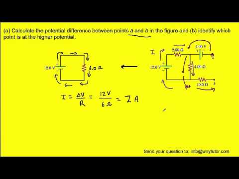
Calculate the potential difference between points a and b in the figure
 0:06:35
In a network as shown in the figure the potential difference across the resistance \( 2 \mathrm{...
 0:04:29
In the figure, an electron accelerated from rest through potent... | Physics Electricity & Magne...
 0:05:49
In the figure below, particles of charge q1
 0:04:21
In the figure, the capacitances are C1 = 1.0 µF and C2 = 3.0 µF, and both capacitors are charged to...
 0:04:12
In the figure what is the net electric potential at point p
 0:07:27
Find the potential difference across each resistor in the figure below.
 0:04:44
In the figure below, what is the potential difference between the point A and B and between B and C
 0:10:17
For the system of capacitors shown in figure
 0:02:41
In the given figure, potential difference between A and B is
 0:11:28
In the circuit of the figure below determine the current
 0:05:33
In the figure the battery potential difference V is 10.0 V and each of the seven capacitors
 0:04:56
In the circuit shown in the figure, the potential difference between points `a and b` is `V_(a)
 0:09:45
For the circuit shown in the figure, calculate (a) the current in the 2.00-Ω resistor and (b) the po...
 0:03:09
In the electrical network shown in the figure, the potential difference across 3Omega; resistanc....
 0:03:47
, , A circuit has a section AB as shown in the figure with E=10 V, C_1=1.0 μF, C_2=2.0 μF and th......
 0:03:43
In the part of a circuit branch shown in figure the potential difference Vab at t = 1s is ....
 0:05:14
In a network as shown in the figure the potential difference across the resistance 2R is
Комментарии