filmov
tv
In the figure below a potential difference v =

Показать описание
In the figure a potential difference V = 100 V is applied across a capacitor arrangement with capacitances C1 = 10.0 µF, C2 = 5.00 µF, and C3 = 15.0 µF. What are (a) charge q3, (b) potential difference V3, and (c) stored energy U3 for capacitor 3, (d) q1, (e) V1, and (f) U1 for capacitor 1, and (g) q2, (h) V2, and (i) U2 for capacitor 2?
 0:11:28
In the circuit of the figure below determine the current
 0:05:49
In the figure below, particles of charge q1
 0:03:53
In the circuit of the figure below, the current I1 is 3.0 A and the values of ε and R are unknown.
 0:02:42
The flexible loop in the figure below has a radius of 12 cm and is in a magnetic field of strength 0
 0:05:54
Find the charge on each of the capacitors in the figure below.
 0:07:22
4.5 | In Figure 4.7, the net external force on the 24-kg mower is stated to be 51 N. If the force of
 0:09:04
Consider the following figure find the equivalent capacitance
 0:05:24
In the figure particle 1 of charge
 0:04:26
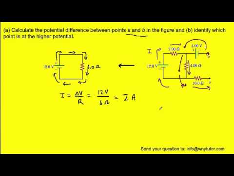
Calculate the potential difference between points a and b in the figure
 0:08:41
in the figure four particles form a square
 0:08:53
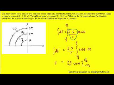
The figure shows three circular arcs centered at the origin of a coordinate system
 0:03:25
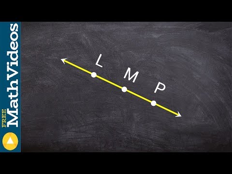
Naming the rays in a given figure
 0:06:12
Microsoft Word: Insert Figure Caption and Table of figures (chapter based)
 0:02:16
Name the segments in the given figure
 0:00:14
Action Figure Thriller Michael Jackson Halloween #shorts
 0:11:12
Using kirchhoff's rules find the current in each resistor shown in figure
 0:01:39
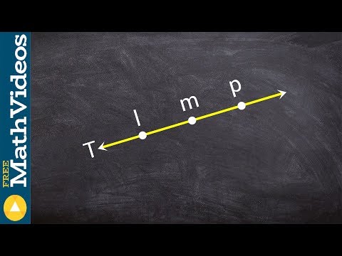
Name the opposite rays in the given figure
 0:00:43
Figure drawing (Anatomy)
 0:01:59
Find the value of x in the given figure.// Important questions - lines and Angles class 7 maths
 0:09:47
In the figure a stone is projected at a cliff of height
 0:07:14
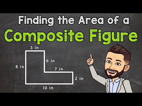
Finding the Area of a Composite Figure | Area of Composite Rectangles
 0:00:07
Should I Buy The Holiday Star Wars Black Series Mandalorian Figure??? #shorts
 0:02:09
Find the Value of X from a Figure Using Alternate Interior Angles
 0:00:59
How long would it take you to figure out this INSANE puzzle cache?!
Комментарии