filmov
tv
In the figure, the capacitances are C1 = 1.0 µF and C2 = 3.0 µF, and both capacitors are charged to

Показать описание
In the figure, the capacitances are C1 = 1.0 µF and C2 = 3.0 µF, and both capacitors are charged to a potential difference of V = 100 V but with opposite polarity as shown. Switches S_1 and S_2 are now closed. (a) What is now the potential difference between points a and b? What now is the charge on capacitor (b) 1 and (c) 2?

In the figure, the capacitances are C1 = 1.0 µF and C2 = 3.0 µF, and both capacitors are charged to...

In the figure the battery has a potential difference of v = 10.0 v

Find the charge on each of the capacitors in the figure below.

Consider the following figure find the equivalent capacitance
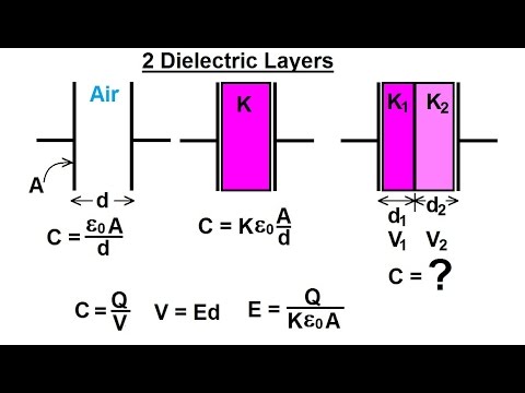
Physics 39 Capacitors (36 of 37) 2 Dielectric Layers
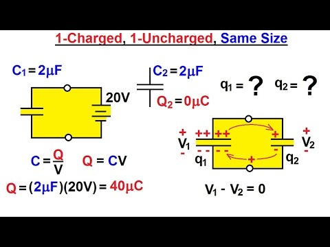
Physics - E&M: Dis- and Re-Connecting Capacitors (1 of 16) 1-Charged, 1-Uncharged, Same Size

Find the charges on the four capacitors of capacitances \( 1 \mu \mathrm{F}, 2 \mu \mathrm{F}, 3...

In an adjoining figure are shown three capacitors C 1, C 2 and C 3 joined to a battery. The correct

Is it in Series or Parallel 🤔 | Dielectric in Capacitor | JEE Physics | Mohit Sir [IIT KGP]

Capacitors in Series and Parallel Explained!

Electrical Engineering: Ch 6: Capacitors (18 of 26) Find the Equivalent Capacitance 2

Find the equivalent capacitances of the combinations shown in figure between the indicated points.

Find the capacitances of the capacitance of the capacitors shown In figure .The plate area is `A

The capacitances and connection of five capacitors are shown in the...

Find the equivalent capacitances of the combinationsshown in figure (31-E15) between

Capacitance Questions Short Trick for JEE/NEET Students #neetphysics #sachinsirphysics #neet2023

Find the capacitances of the capacitance of the capacitors shown In figure .The plate area is `A...

Ch02Q23 (Electric Potential & Capacitance) Assignment Solutions

CAPACITORS IN SERIES AND IN PARALLEL. PAPER 2 PHYSICS

Current through a capacitor

Find Equivalent Capacitance Between A and B.

Short trick for capacitor questions | give answer in 5 second #shorts #ssp_sir

, , A capacitor of capacitance 5 μF is connected as shown in the figure. The internal resistance ......

Numericals on capacitor plates || Capacitor numericals trick || Capacitor numerical adjacent plate
Комментарии