filmov
tv
3 phase motor test

Показать описание
 0:10:58
3 phase motor test
 0:05:59
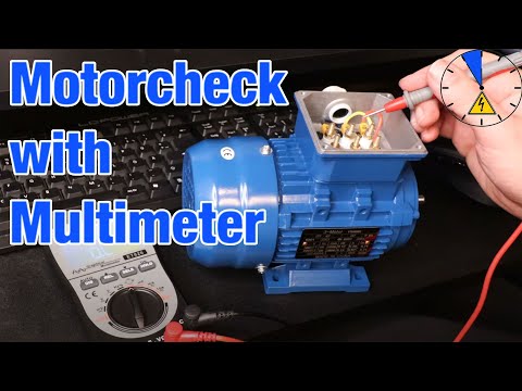
how to test 3 phase motor with multimeter
 0:03:38
How to test 3-phase motor using MEGGER meter ? Winding resistance and insulation test.
 0:03:50
How to test 3-phase motor using MEGGER. Winding resistance and insulation test.
 0:04:37
3 Steps - How to check a motor only with a multimeter?
 0:39:04
3 PHASE MOTOR TESTING - how too PROPERLY
 0:01:46
Phase Sequence/Motor Rotation Tester on 3-Phase Motor [IUEC 394]
 0:15:43
How to check your Electrical motor winding - Continuity & Insulation resistance test
 1:51:10
BSPHCL TG-III, Full Technical Syllabus Free | 3-Phase Induction Motor Lec-16 | @PrarthanaEducation
 0:09:35
Learn Practically How to Check Motor with Insulation Tester @TheElectricalGuy
 0:00:43
Ground Testing - Electric Motor - 3 phase motor
 0:15:34
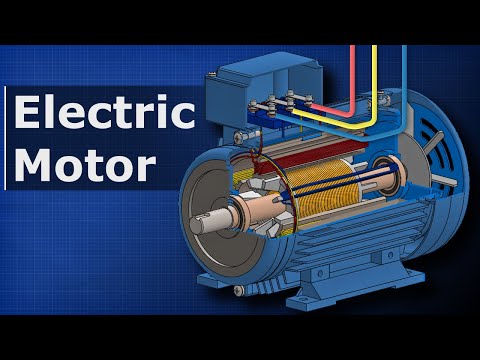
How Electric Motors Work - 3 phase AC induction motors ac motor
 0:02:44
How to Meg a Motor with a Megohmeter - Checking Motor Condition
 0:03:18
Using the FLUKE 1507 to Identify a bad motor.
 0:09:26
How To Troubleshoot 3 Phase Motor With A MultiMeter (3 Phase Motor Test) Winding Resistance Test Ohm
 0:12:41
How to test Electrical motors with a multimeter. 3 phase motor testing with multimeter.
 0:02:37
3 phase motor testing with multimeter / winding good or failure #tamil #winding #resistance
 0:04:08
3 Phase Motor Testing With Multimeter! How to Check 3 Phase Motor! @sn technical
 0:06:16
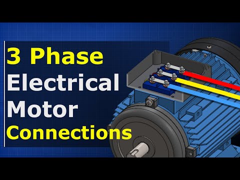
Electrical Motor Connections
 0:02:57
How does ABB test electric motors?
 0:11:45
Troubleshooting 3 phase motors
 0:05:06
How to check a 3 phase motor system
 0:01:17
How To Check 3 Phase Power
 0:07:55
Checking Windings in a 9 Lead 3 Phase Motor
Комментарии