filmov
tv
EEVblog #803 - HP1740A Analog Oscilloscope

Показать описание
Dave saved this classic from the dumpster, a HP 1740A 100MHz dual channel analog oscillocope from the mid 1970's.
It wasn't supposed to be working so this is a look at the problem, a mini teardown, and some basic PSU troubleshooting.
Update: Even after 4 hours it still doesn't fail with the covers off. So likely to be some sort of thermal issue as suspected.
Original HP Journal article on the HP1740A:
Acknowledgments
The 1 740A design group was led by Stan Lang until the start of pilot production when he transferred to another project. The design team included Jim Garner, mechanical design including the vertical
attenuator switch, Eldon Cornish, who designed the horizontal section, and Van Harrison who designed the CRT circuits, power supplies, and gate amplifier.
Support the EEVblog through Patreon!
EEVblog Amazon Store (Dave gets a cut):
Donations:
Projects:
Electronics Info Wiki:
 0:38:55
EEVblog #803 - HP1740A Analog Oscilloscope
 0:50:34
EEVblog #804 - HP1740A Oscilloscope Repair - Part 2
 0:04:55
eevBLAB #70 - EEVblog Impersonation WARNING!
 0:51:42
EEVblog #502 - $19 Hameg Analog Oscilloscope
 0:37:47
EEVblog #812 - Varta 15min NiMH Charger Part 2
 0:45:38
EEVblog #839 - Mailbag
 0:01:08
HP 1740A Oscilloscope - SuperChristmas!2012
 0:56:26
EEVblog #797 - Siglent SDS1000X Oscilloscope Review
 0:29:27
HP 181A oscilloscope 1804A plug in 4ch 50MHz 1820C timebase repair
 0:41:21
EEVblog #1306 (1 of 5): 3 Cent Micro - Open Source Programmer
 0:02:29
The EEVblog Lab VIBRATES!
 0:41:01
EEVblog #1203 - REPAIR: Tektronix 2465B Oscilloscope
 0:49:48
EEVblog #802 - Mailbag
 0:02:00
EEVblog #799 - How To Remove Warranty Void Security Stickers
 0:33:04
EEVblog #791 - Ebay Fluke 45 Multimeter Teardown
 0:11:18
EEVblog #778 - Oscilloscope Vertical Confusion
 0:37:00
EEVblog #845 - Oscilloscope FFT Comparison
 0:19:56
EEVblog #1124 - Rigol 7000 Oscilloscope Teardown
 0:17:02
EEVblog #524 - Vignetting on a Cathode Ray Tube
 0:31:48
EEVblog #853 - How A Multimeter Works
 0:32:30
HP 410C Electronic Voltmeter 1962-1968 test repair teardown
 0:43:00
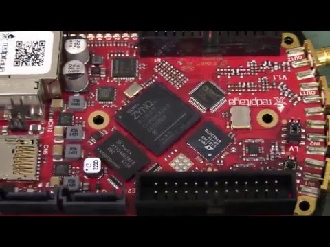
EEVblog #858 - Red Pitaya
 0:03:43
eevBLAB #14 - 14yo Hobbyist Arrested For Bringing DIY Clock To School
 0:40:55
EEVblog #824 - GW Instek GDS-1000B Oscilloscope Teardown
Комментарии