filmov
tv
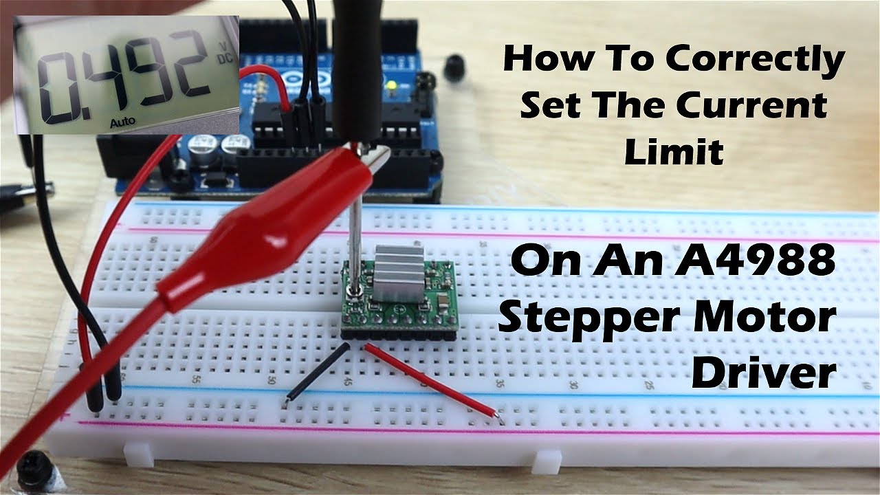
How To Correctly Set The Motor Current Limit On An A4988 Stepper Motor Driver
Показать описание
In this Tutorial video, I'm going to be showing you how to correctly set the motor current limit on an A4988 stepper motor driver. These drivers have become popular for CNC, 3D printing, robotics and Arduino projects because they're relatively cheap and really easy to use, they only require two pins to provide full control of a stepper motor.
There are two methods to do this, the one is to use a multimeter to physically measure the current flowing through one of the coils and the second method, which is the one we’re going to look at, is to calculate adjust the reference voltage on the driver, which doesn’t require the motor to be hooked up or powered.
Components Required
If you've got any Tutorial requests or suggestions, let me know in the comments section below. I'm always looking for suggestions.
 0:00:55
How to Set a Watch Correctly | Guide to Life
 0:16:47
How To Correctly Set Your Mechanical Watch
 0:04:50
How To Correctly Set The Motor Current Limit On An A4988 Stepper Motor Driver
 0:11:53
How To CORRECTLY Set Up The Nightclub to Make MILLIONS | GTA Online Rags to Riches Ep. 7
 0:44:49
How to correctly set up an Electric Guitar - everything you need to know.
 0:04:32
How to Correctly Set Your Torque Wrench - TOTAL TECHNIK
 0:15:24
How to CORRECTLY set a weight loss goal in 2024 | Dr. Dan | Obesity Expert
 0:11:54
How To Correctly Set A Tattoo Needle & 'STROKE' Fully Explained!
 0:01:52
Rowe: Secret Service made 'correct decisions' in Florida
 0:03:10
How to Correctly Set The Table| At Home With P. Allen Smith
 0:07:22
How to Correctly Set Up The Knee Cut Pass
 0:00:59
Tool Tip: How to correctly set the hose size for your CTM MIDI extractor
 0:03:45
How To Set The Timing Correctly - Barina ¦ Cruze ¦ Astra ¦ Corsa 1.6 & 1.8 Engines
 0:00:57
How to correctly set the airflow in your spray booth
 0:04:25
Working from home - How to set up your laptop (correctly!) | Tim Keeley | Physio REHAB
 0:05:41
How To Correctly Set the Deck Wheels on a Riding Lawn Mower Tractor
 0:04:36
How To's - Correctly set the angle of your table saw
 0:00:38
Correct set-up for Driver 🏌🏽♂️ #stackandtilt #golftec #gridlife #optimotion #hackmotion #teeclaw...
 0:00:33
Set Shower Valves to Correct Depth - #shorts
 0:06:11
Here Is How To Correctly Set Goals | Andrew Huberman
 0:09:08
Elementor Global Settings Explained - How to Correctly Set up the Site Settings for a Great Workflow
 0:09:35
The Correct Wrist Set Simplifies Your Golf Swing
 0:00:45
Correctly set sag on your MTB fork. Full setup video below👇
 0:03:47
How To Correctly Set Up The Timing Chain And Cams On A Toyota 2.4 L Engine
Комментарии