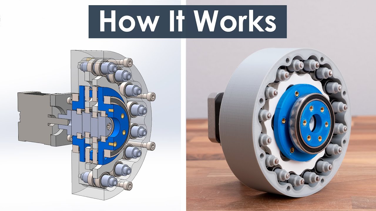
What is Cycloidal Drive? Designing, 3D Printing and Testing

preview_player
Показать описание


Parts list (check website article for full list, affiliate links):

AliExpress:

Like my page on Facebook:
Рекомендации по теме
Комментарии
Автор

Clean design. Clear and instructive explanation. Evaluated the results of the work. Original Content. Material list included. 3D Model included. Perfect video honestly.

simeon
Автор

What a SPLENDID video showing such a brilliant design. I am a bit amazed at the accuracy you got from the 3D printer.

EldonElledge
Автор

This is an absolutely beautiful design! Keep up the outstanding work!

louvoodoo
Автор

This mechanism was my master's work during studying process, but yours is the best.

ВладиславКузин-бч
Автор

1. You can draw parametric curve from 0 to 180 degrees, then connect it's start and end, extrude half of the cycloid, and then just mirror it and get full shape.
2. It's better to use SolidWorks variables. This way you can change cycloid's shape much easier.
3. Efficiency was measured incorrectly. Does this motor really produce rated torque? Input torque should have been measured before measuring output torque.
And it's also interesting how much torque will this reducer handle before something breaks. :)

TheNamelessOne
Автор

James Bruton used Cycloidal Drives in his most recent version of the robot dog. And I somehow doubt that it did not inspire you a little.
It's worth checking out

Angel-vcbw
Автор

Your channel is just amazing!! This deserved a scara pic and place with computer vision detecting objects!

joaocamiloulhoa
Автор

Excellent as usual! I never expect anything less from your videos.

rdyer
Автор

that was quite beautiful. elegant mechanics.

jasonbenjamin
Автор

In the first seconds of the video I thought the scene was a 3d rendering, so clean it is !!! until I saw your hand grabbing the device. Nice video and valuable content !

visualchallenge
Автор

About the shaft :
when screwing pla parts together, I avoid using purely undersized holes : there will be a lot of friction wich will generate heat when screwing, risking to damage the part.
a common option is to use threaded inserts, but they are expensive and not always usable (tiny space for a screw, for example)
personally, for 3mm screws (just for reference, my engineering project uses non less than 41 m3 screws all holes made with the following method) : a 2.3-2.4mm hole in the 3d model, that hole is re-drilled with a 2.5mm bit (inner diameter of M3, M5 is 4.2, for reference) with a cordless drill at slow speed to avoid melting the PLA, the hole gets a perpendicular exit (through part hole / I had in the model an other hole perpendicular at the end of the screw's hole) to make an exit for the debris, lastly the hole is slowly hand-threaded with a M3 tap and tap holder with a 2 turns down, half turn up, movement, to limit friction and let debris go down to the exit. If the hole is deeper than 15mm, I firstly do a 10mm pass, remove the tap and clear debris with a straightened paperclip, to much debris will make a lot of friction, heating up the pla and ruining the thread, so go slowly.
Uses and personal recommendations :
Fixing a pcb : a m3, 6mm long thread is enough.
Fixing plastic parts together : a 10-15mm long thread is enough

aterxter
Автор

I'm an electrical engineer brought here by a chance, however I do have certain appreciation of the mechanical engineering.
I am able to judge that this video presents an extensive engineering effort, showing itself both overall and in the details.
I wish I could work with you on my energy conversion related projects (quite a lot of mechanical engineering is required there), or that my mech. engineers could represent at least a half of your ability and attitude to the subject.

e.s.
Автор

Beautifully done project! A transparent cover would be cool for showing what’s happening inside and dust protection.

NicleT
Автор

Could you add a link to the paper with the equation pls?

oferliberman
Автор

I've made two of Mechatronics projects, the Mars Rover and the Scara Robot Arm. These projects are great because they are well thought out and designed, with lots of photos and construction details. Looking forward now to make one of these drives to learn about it and maybe use it in a different Scara robot arm. Good stuff Dejan! Thanks for this.

queenidog
Автор

Hey all, just FYI, the equation as copied and pasted into SW had some issues. I copy and pasted it directly into SW2022 and it came up with something that looked more like a flower than a gear. After watching a video on Stepbystep-robotics channel I was able to figure it out. He had done some intermediate calcs on a couple of the terms and then replaced those terms in the equation and removed the associated parentheses that are no longer needed. This solved the problem. Also, in SW you can use the equation editor to lay out your terms and then put the equation into the sketch using the terms with, with " around each term. This makes your disk editable without having to re-copy/paste the equation in.

brandonb
Автор

Can you recommend one or a substitute that will last decades?

lIII
Автор

Great job! Thanks for sharing with us !

Rafitas_
Автор

This video can really add value to the other old industrial applications . Great work👍

sarabvirdi
Автор

OMG Thank you so much for uploading this video
Now I understand how to drive it

Frog_cousin