Harmonic vs Cycloidal Drive - Torque, Backlash and Wear Test

preview_player
Показать описание


Measuring tools used in the video (affiliate links):
Amazon:
AliExpress

Parts list (check website article for full list, affiliate links):

AliExpress:

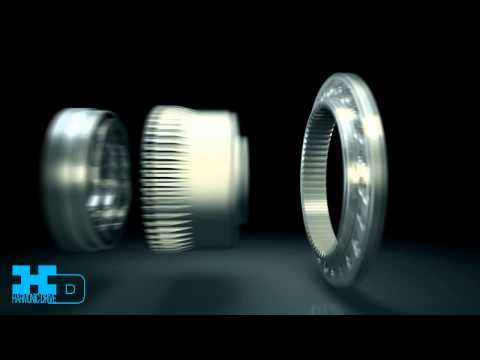
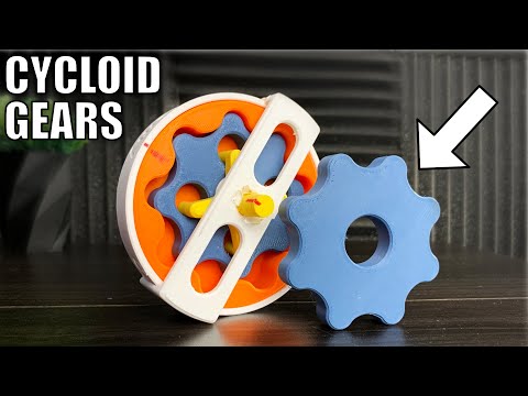
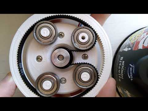
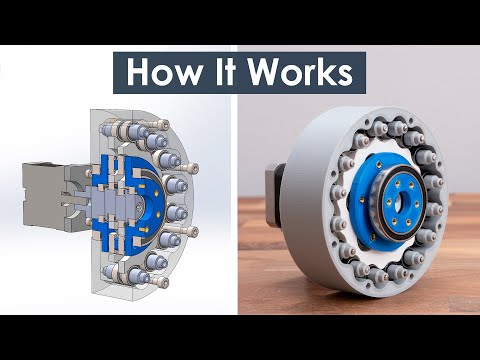
In this video we will find out what’s better, a 3D printed harmonic drive or a 3D printed cycloidal drive. Here I have these two gearboxes or speed reducers that I made which have the same size and reduction ration of 25:1. I will compare them in several categories, measure their efficiency or torque output, measure their accuracy or backlash, and see how durable they are.

I will explain how I designed and assembled both of them, and I will give you some useful tips and tricks for 3D printing them, show you what can go wrong and what can we improve to get them better, things that I have learnt along the way of making several of these.

Actually, this is my 4th video talking about these gearboxes, and why is so? Well, these gearboxes are good choice for robotics applications and in future videos I plan to make some robots that will employ this type of gearboxes.

00:00 What are Harmonic and Cycloidal Drives?
02:13 Designing
07:56 3D Printing
09:09 Assembling
15:02 Backlash Comparison
16:25 Torque Comparison
17:46 NEMA23 Torque
19:56 Verdict

Like my page on Facebook:
Рекомендации по теме
Комментарии
Автор

You should throw a planetary gearbox in there as well and use it as a baseline.

Dazdigo
Автор

I tried to 3d print small S springs in PLA for a circuit probe and found the PLA would brittle fracture if left under strain over night, and otherwise lose flexibility eventually. I switched to PETG and have yet to break the S springs. Might give PETG a try for the flex spline. It's more sticky than molten PLA, but doesn't require a heated enclosure like ABS.

Excellent video presentation. Bravo.

charetjc
Автор

For the Australian Rover Challenge I used a flexspline that was printed in solid TPU of 95A Shore hardness and it performed really well. This choice was landed on after a significant amount of testing.

nigelhungerford-symes
Автор

For the flex spline, it is something that need to flex, so I would definitely go with TPU or Nylon, PLA is nice for prototyping and part that needs strength but not for flexibility.

Anyway this is a really interesting test, I'd love to see it with a different material for the flex spline.

damienmartinguillerez
Автор

That outcome really shocked me, in terms of durability over time. When I first saw them both in operation, the cycloidal looked like it had more flex and strain on some parts. But thank you, I’m not sure why this showed up in my feed, but it did and I learned something!

victisomega
Автор

Now that you have created wonderful 3d printed prototypes to prove the concept, I'd love to see this taken to the next stage, and produce metal parts, either from CNC parts, or maybe testing out parts made from metal 3d printers.

Great work on all this.

Designbyapro
Автор

Dude you're killing it. I need to work with you or for you. I love the delivery and competence and clarity. Nice walk through the progress of logical thought. Ontop of the work you kindly made a video. Thank-you

adamrowsell
Автор

We are using harmonic gearbox with 80:1 ratio as a phase adjustment device between two or more rotary axes on printing presses. There are many different cases where these compact gearboxes are used for other than just speed reduction. You can cover those cases at some point of time. That would broaden your viewers perception of gearbox.

tctn
Автор

Been a subscriber for a long time. Your stuff gets more and more technically sophisticated. 👍👍

rdyer
Автор

I’ll have to go watch that Cycloidal drive video after this one - I used to work in a factory that made cycloidal drive three phase motors, and I always wondered what was so special about the cycloidal drive

EclipseAtDusk
Автор

The amount of deep work to achieve this result is crazy
respect

hafiz
Автор

I think that you can increase the durability of the flex spline if you add a radius of 2 or 3 mm in the bottom of the cup around the wall.

jonamr
Автор

To be totally fair, the cycloidal drive has quite some metal parts, which the harmonic drive don't. Also, the size is optimized for the cycloidal drive, not for the harmonic drive. I suppose an harmonic drive with longer deformation, could even have smaller diameter and get better result. Also, the joint between the back and the side of the harmonic inner gear (the one breaking), could be reinforced in many ways.

escain
Автор

I think they are both great if made of right types of steel, and not plastic.
They are very compact and expensive, but zero backlash is what they are also known for.

piconano
Автор

the teeth on your flex spline are pretty big. You can probably get them down to MOD 0.8 which will reduce the amount of deflection the flex spline will need to undergo AND increase the gear ratio per the same gearbox diameter. Also, try making a elliptical bearing with BBs like the youtube ZeroBacklash does with his strainwave drive gearbox.

dylanpendlebury
Автор

Nice,
and greetings from Germany.
Best for 2023 :)

mircon
Автор

You probably do not need any "Expansion" setting, they are not needed to get dimensionally good prints. Most important setting is (if you're using Cura, I don't know in other software) the "Slicing tolerance" set to "Exclusive". I was struggling like you with prints until I changed "Slicing tolerance" setting from "Middle" to "Exclusive" end now every print is perfect to the 0.05 I would say (I tested some clearances changing by 0.05, and you could tell that there was change). You can find this setting in "Experimental" section in Cura. Even 3D printed threads right from the Fusion 360 are working righty away without any change in clearances.

This "Horizontal expansion" setting, as many other settings, was created when 3D printing was at its beginnings. People back then tried to solve problems in not always to say the best ways. And now these settings still are there, but they are not really have to be used nowadays.

There was a video explaining that phenomenon on YouTube but unfortunately I Forgot channel and name guy who made it. Maybe someone reading that can comment below the link.

EDIT: Of course for this to work printer have to be calibrated (e-steps)

maciejpospiech
Автор

Test the harmonic planetary drive! I think it's better than both. It's a harmonic drive that can be made with completely rigid parts. Two ring gears of the same diameter with tooth counts differing by one, one of them fixed and the other connected to output. A rotating input carrying (at least) three spur gears around in contact with both ring gears. Two of the three spur gears have teeth out of phase by one-third of a tooth, but all have the same number of teeth in contact with both rings. Reduction ratio is equal to the tooth count of the output ring.

zrebbesh
Автор

Thank you very much for this great video.
Little Tipp: You could try to shrink the length of the teeth on the harmonic drive, so you don't need to stretch the material that much.
Also it might be a good idea, to use 1 bigger bearing instead of 3 (or one) smaller ones, to stretch the pressure / load.

MaxMustermann-smqu
Автор

If you plan on properly (and by that I mean more thoroughly) testing the harmonic drive principle you might take a look at the less known double rigid external gear config (one with 50 and one with 48 teeth, exactly as many as the belt flex spline). For the same compactness of the design you're getting a much higher torque...

ErosNicolau