EEVblog #483 - Microcontroller Voltage Inverter Tutorial

preview_player
Показать описание
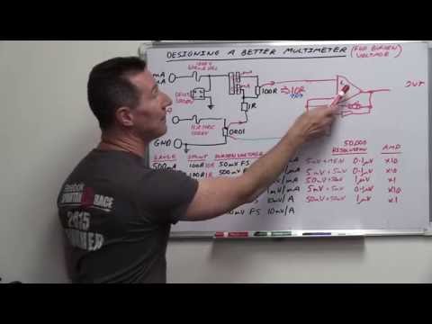
How a diode voltage inverter circuit works.
Turns any PWM or clock signal into a low power negative voltage rail.
This can be clocked from a microcontroller, existing DC-DC converter, 555 timer etc.

EEVblog Main Web Site:
EEVblog Amazon Store:
Donations:
Projects:
Electronics Info Wiki:
Рекомендации по теме
Комментарии
Автор

It is worth noting that the same principle of cascading stages of a CW doubler/multiplier applies here. I just put together a 2-stage voltage inverter that provides about -6.2V from USB's +5V, and -5.9V at around 15mA of load with negligable ripple (circa 10-12mV); plenty for driving an opamp. Caps are 330uF/16V electrolytic, diodes are BAT46 schottkys, ~6.8kHz square wave drives a 2N3904/2N3906 pair. Could be more efficient without the transistors, but I wanted to isolate from the PIC12's 50mA pin. Altogether less than $1US worth of parts. Great video, very helpful.

markm
Автор

try to build circuits from time to time just for fun, I find that doing stuff alone helps you learn a lot about the components and you also learn what working techniques works for you.

don't be afraid to look at datasheets, they can really help you out some times.

svampebob
Автор

Haha.  I love how you tell about the concept so clearly, then basically say, "but don't worry about it!"  Many levels of awesome.  Thanks.

JWalterHawkes
Автор

I love your tutorials Dave. I learn something while haveing my lunch. And come back to work with the knowledge that i at least learned something today.

metalmolisher
Автор

When Point 1 is high the diode is forward biased and conducting, so it "steers" or "pulls" point 2 to ground (or one diode drop above ground).

EEVblog
Автор

I see you've renewed your DaveCad licence. Must've cost a fortune ;-)

zupnikal
Автор

Dave, when going through the voltage doubler, next you should do it going through the tripler. This is a clever design where multiple circuits can be connected in cascade and voltage can be multiplied millions of times.
Used in old TV's to generate high voltage for CRT

mondeo
Автор

Very true, keep in mind I'm mainly talking about higher current need situations. If you just need a few mA to throw +-10V at an opamp or something like that, going discrete is a fine solution!

Needing a uC for a PWM output is the only issue I have with this method. Could you perhaps show a cheap and simple way to generate a 50 to 100kHz pulse for this (without using a micro)?

timbdotus
Автор

Hey!!  Question for you..  I know you say that this only permits a few tens of amps.  What if we instead drove an NPN transistor rated for, say, 2 amps from the input square wave and upped the diodes to 1/2 watt diodes.  Additionally, imagine that the collector on the transistor has an input of +15 volts.

It seems that this should allow us to drive a 555 square wave from a 5 volt source and invert a +15 volt supply and get at least 1/2 amp out of it.  Thoughts?  I'm not much of an electronics engineer but I have a need to build just such a circuit!!

Thanks!

DHAtEnclaveForensics
Автор

50 cents can be a big part of your BOM cost if you are watching the cents. Also the cheapest 100mA one Digikey have is is the MAX660 at $0.61 in 2500 volume. If you don't care about cost, sure use a switched cap chip.

EEVblog
Автор

In huge quantities, cheap diodes and caps end up costing a couple of cents each. Since you're already ordering them, adding a couple more per product lets you pocket that extra 45 cents on each unit, or buy better knobs that aren't crap or something.

toast_recon
Автор

The TPS60151 is $0.50 direct from TI in 1k quantities. I don't disagree that a discrete solution can be cheaper, it's just that at higher current ranges the single chip solution really closes that cost gap. Plus it's a simpler, more reliable design and you get extra features like soft start, shutdown and power good outputs. Not to mention the fact that they can switch in the hundreds of kHz to help prevent ripple.

timbdotus
Автор

say you have a cap, charge it at 5V, then hook the positive lead to ground, on the negative lead you should measure -5V from ground, now put a diode and another cap which is referenced to ground (and discharged) conected to that -5V, the second cap should (dis)charge to -5V, now just repeat.
That's what happened, but instead of doing it manually, the second diode which has connected directly to ground did it. Imagine the current flow, and you should see how the diodes do the job.

laharlk
Автор

Nice, fundamentals Friday...can't wait to next Friday ..

ver
Автор

Inductors don't change their current instantly. If the capacitors are replaced with inductors, would the circuit operate on the current rather than the voltage? What characteristics would it have, ie would it double the current?

Knight
Автор

If it is for a product, I can agree, go find some of the shelf component and done.
But this is my situation: I'm using a protoboard with a 16x2 LCD + 3.3V micro battery powered. Not making the product yet, just trying stuff. And the LCD is the only one requiring 5V. Then at this moment I can't think a better solution than using a Dickson doubler or the inverter.
See Ramtron an502.
In the end, the situation "choose" the solution.

elcolotronics
Автор

when was the voltage inverted in the video? I just see a voltage double type of circuit, the type that we saw before in a previous video.

MatrixOfDynamism
Автор

Hi Dave, Can you please next time, explain the Op Amp configuration in order to perform any kind of linear conversion ? I mean, for example, with an Op Amp, convert 2-8 into 0-5V and those kind of conversions... those are cool circuits that are pretty useful..

CxC
Автор

There is a practical limit; you aren't going to pull half an amp using crap parts and this simple design. Plus the higher you go in frequency, the more inductance on your traces/leads matters. You're also going to have problems with using standard 1N001 diodes because of switching losses.
If you need a negative source with lots of current capability, you're probably better off grabbing a shelf part than dickering around with discretes.

bloomtom
Автор

Is there a practical limit on switching frequency? If you get into the MHZ range, can you support an even higher load with the same crappy parts? What would it take to drive say .5A?

TomMinnick