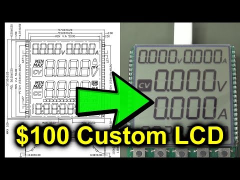
EEVblog #1046 - Mysterious Digital Voltage Doubling (LCD design)

preview_player
Показать описание
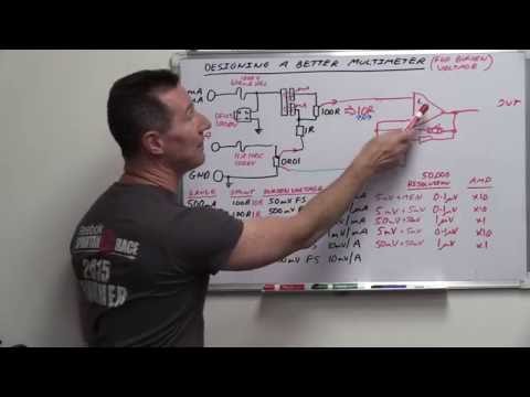
Dave explains and demonstrates how out of phase digital signals can effectively double your voltage. The magic of moving your reference point. And how you can verify this with a differential probe.
A question bought up in the comments of the previous LCD driving video.

The HVP70 High Voltage Differential Probe
Coupon code "bargainprobe"

Support the EEVblog through Patreon!

Donate With Bitcoin & Other Crypto Currencies!

EEVblog Amazon Store (Dave gets a cut):

Рекомендации по теме
Комментарии
Автор

For those that are still struggling to understand, try this. Imagine you have a speaker, you apply 5vdc, the speaker cone moves out and stays there right? Now remove the 5v DC and the cone returns to its resting point right? Now reverse the wires and apply 5vdc again, this time the cone moves IN right? Now, how many volts AC, peak to peak, would move the speaker cone the equivalent distance max out, to max in? Have a guess.

SimoWill
Автор

You've got 10Vpp BUT you've still got 5VRMS. For me it's not a voltage doubler. However if you add a diode and a capacitor then you'll get 10VDC and you now have a charge pump voltage multiplier. Note that 1.5v calculators use this kind of voltage doubler to generate 3v for the digital logic and to drive the LCD. On dot-matrix LCDs the controller also uses this kind of voltage multiplier to generate voltage up to 15 volts or more in order to achieve a good contrast.

atmel
Автор

If you measure 5vdc with a multimeter then swap the probes over you will see -5vdc.
This is basically what this circuit is doing - alternating between 5vdc and -5vdc resulting in 10v peak to peak.

alanesq
Автор

I'll just put a copy of my response to the comment on the other video, in case it helps someone:

At time t0:
COM is at 0V relative to circuit ground
Pin A is at 5V relative to circuit ground.
Pin A is therefore at 5V relative to COM.

At time t1:
COM is at 5V relative to circuit ground.
Pin A is at 0V relative to circuit ground.
Pin A is therefore at -5V relative to COM.

In other words, Pin A just went from 5V to -5V relative to COM, which makes a change of 10V.

Yotanido
Автор

I had the exact same thoughts and questions when I watched the last video. But I paused the video, thought about it for a while, rewatched dave's explanation, rewatched the scope example, looked at it from a different point of view, and suddenly it became clear. I thought I was just slow, I didn't realize others would actually call you out as wrong or misleading. Its like staring at an optical illusion for a while then suddenly seeing it clearly.

flubba
Автор

It's simple, the scope is measuring relative to it's Gnd reference (the Gnd clip). When the Reference voltage on the Gnd clip is 0V and the probe is at +5V the difference is a +5 Volts. Now, the confusing part. The logic is changing the voltage at the Reference Point (The Gnd Clip) to +5V and at the same time the probe is now at 0V. Zero is below 5, the result is that the measured Value is now -5V. You end up with a +5v to -5v Differential swing on the scope. BUT, it is still a 5 Volt Peak to Peak signal relative to the logic circuit (no voltage doubling) the AC RMS is 2.5volts, you only end up with a "SIMULATED" -5Volts because the COM of the LCD is Floating relative to circuit com and not at a fixed reference point. Your single ended voltage is still 5 Volts no mater the polarity (of a single signal). It is simply the function of TWO different wave forms that give you the 10Volts (remember the LCD's com pin is floating). The Differential AC RMS of the to signals is still 5V. No doubling took place ;-)

It's also worth mentioning that each segment of the LCD would have its own XOR gate, wired exactly as the one shown for segment A. In this way, all the driven segments will change polarity relative to the LCD's Com pin at the same time. Effectively driving the LCD with an AC Square wave. With current flowing from com to segment pin and then having the current change direction and flow from Segment pin to the Com pin (exactly as an AC Signal would).

Marzec
Автор

Here is a short note for those who still find it confusing... :)

Easiest way to understand it is, let's have the two points called A and B, where probes are connected in this video.
For first half cycle, A = 5V, B = 0, and for half second cycle, A = 0V, B = 5V

If we call A our "ground reference", A must always be considered 0V.
This makes B look like -5V in the first half cycle (because B is ALWAYS 5V less than A in first half cycle.
In the second half cycle, B is 5v higher than A, which makes it +look like 5V. So you effectively have B swinging from -5V to +5V, with respect to A.
Why A? Because that's where the LCD COM pin was connected to!

mcuembedded
Автор

Hi Dave, I've agreed with every video you've made ... until now. It's not voltage doubling. It's just alternating 5 V across the load one way and then the other way. Your explanation gives an impression that there will be 10 V across the load (between those 2 test points), but in reality, there's only 5 V potential at any given moment. It's just that the polarity changes. If you hook up the scope this way, you'll see what you see, I completely agree with that, because your reference is constantly changing. Another thought experiment: if we hook up 1k resistor between those 2 test poins, what will be the power loss on that resistor? I'm saying 25 mW (that's equal to constant 5 V across 1k (0 V on one end and 5 V on the other for 50 % of the time and then the opposite for another 50 % of time)), but according to your reasoning, you'll probably say 50 mW (which would be equal to constant 10 V from your "voltage doubler"). What is correct?

martin.winkelhofer
Автор

In common inverter technology, this technique is known as "full bridge" by comparison to the classical "half bridge" structure. It involves four switches and is equivalent to revert voltage and current in the load (then here alternating from +5V to -5V). However it is not usually called a voltage doubler as there is no way to obtain a 10V voltage relative to a common ground without using a storing capacitor somewhere. So voltage doubler: yes and no, everyone is right !

henribondar
Автор

Another way to look at it, is in terms of current flow. After all that is what makes it a negative voltage.
A -> B +5V
B -> A -5V
You can also show this differential signal by measuring the current, say by adding a resistor in the circuit and measuring the voltage across it using the scope.

station
Автор

It's just like taking a stereo amp and putting it into bridge mode and wiring the speaker across the two outputs.

russellhltn
Автор

The same trick is used in car audio amps. Due to 12V power limit they use bridge sircuit to drive loudspeekers. So it is possible to get 24 volts on the output peak to peak.

ranikeev
Автор

Actually 10V voltage SWING (difference between minimum and maximum amplitude) doesn't mean 10V VOLTAGE. Actual voltage is +/-5V, but not +5V and -5V AT THE SAME TIME, so not +10 nor -10V differential. But the SWING is definitely 10V.

FilipMilerX
Автор

This should be studied in schools, after 10 years from graduating I saw this first time and this has to be something fundamental; It really changed how I look into circuits thanks really,

yabgu
Автор

I think the problem people have is tied to thinking about ground and common. Much easier just to think about pin 1 and pin 2. Then its relatively simple. Two alternating options,
Pin 1 2
Option 1 = 0V 5V
Option 2 = 5V 0V

There is only ever 5V relative to ground, but the LCD is not connected to ground and doesn't know this. As far as the LCD is concerned its got a push-pull alternating 5V alternating signal across it. This is a 10V peak to peak.

This is rather useful beyond driving LCDs. For example if you are driving a loudspeaker with a 12-14V supply like in a car. The peak voltage available is ~12V. If you were to drive the speaker with a single amplifier like a TDA2003, with one side of the coil connected to ground, you could only have maximum of 12V across the coil. That's 6V peak to peak AC or 4V RMS and with a typical 4 ohm speaker only 4W of audio power, not enough if you own a Landrover. If you instead drive the speaker with two amplifiers, in antiphase with the speaker coil between them, as in the LCD example, you have up to 24 volts available, 8V RMS and 16Watts. This is called a Bridge amplifier. There are more exotic solutions, to high power audio from 12V, that this was one of the most common before switching amplifier chips became commonplace.

mikewillis
Автор

The simplest way i can think of explaining this is by taking a battery and alternate between connecting it backwards and forwards between the probes.
This is essentially exactly what the circuit is doing with the inverters.

DOOMDUDEMX
Автор

Dave, honestly, this is the type of topic/video I love to see on eevblog. Same for the reference to your scope gnd ref video. These sometimes not so intuitive aspects are my preferred topic. I would subscribe to this chan again if there was such a thing. :)

The key to this "mystery" is probably the reference to the inverted signal as the signal levels are switching simultaneously in opposite directions, effectively doubling the voltage (relative to the LCD and w/o gnd ref). And as you already mentioned in the last video, the LCD only wants to see the difference in potential on one pin relative to another. GND is irrelevant here.

Thanks, again, and thumbs up!

mcflapper
Автор

new drinking game. every time dave says "actually" take a shot. if you can still understand the video by the end you win

gigglesseven
Автор

You could think it like this: You have the two square waves, out of phase, each on its own 5vpp. If you change the reference point to be one of these square wave outputs, you have to re-draw the voltage waveform for your new reference point, i.e., flatten it. This new flat line represents your new 0v. And since you flattened one wave form and the voltage difference did not change, your other wave form will be amplified. And since we consider our first output as the 0v (let's call it pin A), we see the inverted output (pin B) flipping from +5v relative to it (logic drives A low and B high), to -5v relative to it (logic drives A high and B low), giving us a total of 10vpp.

PenZon
Автор

It works! I just simulated it with LTSpiceXVII. Input signal = 5 volts at 1KHz, outputs labeled A and B, 10 V P-P displayed by taking V(A) - V(B) which displays as 10V P-P at 1KHz.

TheBdd