filmov
tv
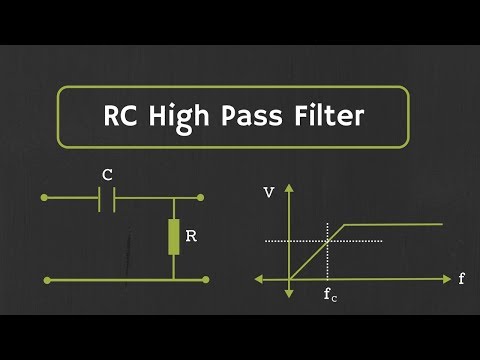
RC High Pass Filter Explained

Показать описание
In this video, passive RC High Pass Filter has been discussed.
What is electronic filter:
The electronic filter is the circuit, which passes some range of frequencies of the input signal and rejects or attenuates the unwanted frequencies in the signal.
Based on the range of frequencies which is being passed by the filter, there are 4 different types of filter.
1) Low Pass Filter
2) High Pass Filter
3) Band pass Filter
4) Band Reject Filter
What is High Pass Filter:
A high-pass filter is an electric circuit, which passes the high-frequency components in the signal and rejects or attenuates low-frequency components. So, the ideal high pass filter passes all high frequencies starting from the cut-off frequency (fc) up to the infinite frequency, and it rejects all low frequencies which are less than the cut-off frequency (fc).
But the actual high pass filter does not support all high frequencies up to infinity. The actual response depends upon the electrical components used in the circuit. So, the maximum frequency supported by the high pass filter depends upon the electrical characteristic of the circuit.
Now, based on the components used for the design, this high pass filters further can be classified into 2 categories.
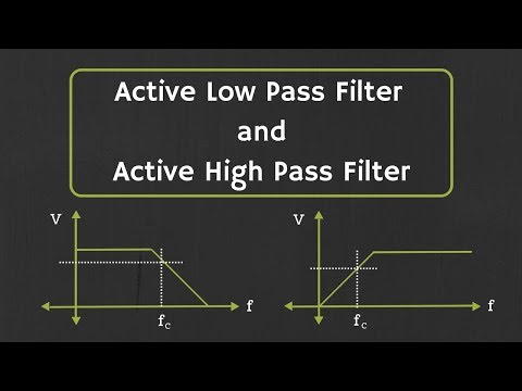
1) Active High Pass Filter:
If the filter is designed using the active components like Op-Amp and transistors then such filters are known as active high pass filter.
2) Passive high Pass Filter:
If the high pass filter is designed using the passive components like R, L and C then such filters are known as passive high pass filters.
These are the most common types of Passive Low Pass Filters.
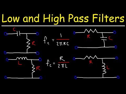
1) RC High Pass filter
2) RL High Pass Filter
3) RLC High pass filter
So, in this video first order RC High pass filter has been discussed and at the later part of the video, it is shown that how by cascading first order high-pass filters, we can design higher order filters.
The order of the filter can be defined by the number of poles in the transfer function of the filter.
(One simple way to find the order of the filter is to calculate the number of reactive components in the circuit, i.e capacitor, and inductor, but always it is not true. There might be some exceptions)
But in general, this procedure can be followed.
The time-stamped link for the different topics in the video is given below:
0:30 RC High Pass Filter
2:27 Frequency Response of first order high pass filter.
3:11 Derivation of cut-off frequency expression
5:03 Derivation of Phase expression for high pass filter
7:10 Phase vs Frequency curve for first order high pass filter
7:56 Example on High Pass Filter
12:05 Higher order filter design by cascading first order filters
This video will be helpful to all students of science and engineering in understanding the RC High pass filter.
Follow me on YouTube:
Follow me on Facebook:
Follow me on Instagram:
Music Credit:
What is electronic filter:
The electronic filter is the circuit, which passes some range of frequencies of the input signal and rejects or attenuates the unwanted frequencies in the signal.
Based on the range of frequencies which is being passed by the filter, there are 4 different types of filter.
1) Low Pass Filter
2) High Pass Filter
3) Band pass Filter
4) Band Reject Filter
What is High Pass Filter:
A high-pass filter is an electric circuit, which passes the high-frequency components in the signal and rejects or attenuates low-frequency components. So, the ideal high pass filter passes all high frequencies starting from the cut-off frequency (fc) up to the infinite frequency, and it rejects all low frequencies which are less than the cut-off frequency (fc).
But the actual high pass filter does not support all high frequencies up to infinity. The actual response depends upon the electrical components used in the circuit. So, the maximum frequency supported by the high pass filter depends upon the electrical characteristic of the circuit.
Now, based on the components used for the design, this high pass filters further can be classified into 2 categories.
1) Active High Pass Filter:
If the filter is designed using the active components like Op-Amp and transistors then such filters are known as active high pass filter.
2) Passive high Pass Filter:
If the high pass filter is designed using the passive components like R, L and C then such filters are known as passive high pass filters.
These are the most common types of Passive Low Pass Filters.
1) RC High Pass filter
2) RL High Pass Filter
3) RLC High pass filter
So, in this video first order RC High pass filter has been discussed and at the later part of the video, it is shown that how by cascading first order high-pass filters, we can design higher order filters.
The order of the filter can be defined by the number of poles in the transfer function of the filter.
(One simple way to find the order of the filter is to calculate the number of reactive components in the circuit, i.e capacitor, and inductor, but always it is not true. There might be some exceptions)
But in general, this procedure can be followed.
The time-stamped link for the different topics in the video is given below:
0:30 RC High Pass Filter
2:27 Frequency Response of first order high pass filter.
3:11 Derivation of cut-off frequency expression
5:03 Derivation of Phase expression for high pass filter
7:10 Phase vs Frequency curve for first order high pass filter
7:56 Example on High Pass Filter
12:05 Higher order filter design by cascading first order filters
This video will be helpful to all students of science and engineering in understanding the RC High pass filter.
Follow me on YouTube:
Follow me on Facebook:
Follow me on Instagram:
Music Credit:
 0:13:23
RC High Pass Filter Explained
 0:05:33
RC High Pass Filter Explained | Passive filter
 0:05:51
Passive RC high pass filter tutorial!
 0:09:55
How High Pass Filters Work using a Resistor and Capacitor (RC)
 0:18:28
Low Pass Filters and High Pass Filters - RC and RL Circuits
 0:32:14
RC High-Pass Filters Explained - Phil's Lab #122
 0:02:27
RC High Pass Filter Explained
 0:07:06
RC Low Pass and High Pass Filter Design and Practical Use
 0:04:58
High Pass Filters: THE MOST COMMON TOOL IN AUDIO PRODUCTION
 0:01:25
Low pass, High pass, Band pass and Band stop filters explained
 0:00:45
Why High-Pass Filters Are Ruining Your Mix
 0:10:28
First Order RC High Pass Filter | Construction, Working, Cut Off Frequency | Simplified
 0:00:27
RC Low Pass Filter #electronics
 0:00:33
Filter Types Explained In 30 Seconds
 0:08:37
How Low Pass Filters Work
 0:00:15
high-pass vs low-pass
 0:00:12
How passive high pass filter work in electronics circuit
 0:14:46
RC Differentiator/RC High Pass Filter(English):Output Voltage, Frequency Response and Limitations
 0:16:33
Active Low Pass Filter and Active High Pass Filter Explained
 0:15:17
Low-pass and High-pass Filters (Explanation and Examples)
 0:05:17
RC High pass filter circuit | circuit diagram I Breadboard wiring| Practical Lab experiment
 0:04:33
RC High Pass Filter LTSpice | Passive High pass Filter using LTspice | Simulation and Calculation
 0:15:18
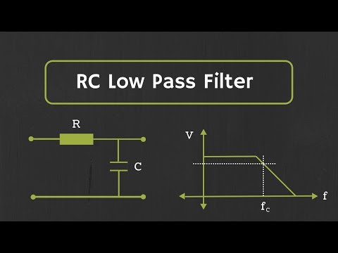
RC Low Pass Filter Explained
 0:00:13
How passive low pass filter work in electronics circuit
Комментарии