filmov
tv
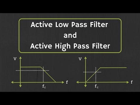
Active Low Pass Filter and Active High Pass Filter Explained

Показать описание
In this video, Active Low pass Filter and Active High Pass filters have been discussed.
What is Active Filter:
The active filter is the electronic filter which is designed using the active components like Op-Amp and transistors.
So, in this video, active filters which are designed using op-amp have been discussed.
Advantages of Active filters: (Disadvantages of passive filters)
In case of passive filters, the gain will be always less than 1, or in other words, the output will be always less than the input.
Also, when multiple stages of such passive filters are cascaded then the overall output will be attenuated severely.
The cut-off frequency of such passive filters also depends on the load. Depending upon the load, the cut-off frequency will be shifted slightly.
All these problems can be overcome by using the active filters.
So, active filters not only provides the gain to the input signal, but they also act as a buffer and isolate the load from the input filter circuitry. (Particularly, when they are designed using op-amp)
In this video, active low pass and active high pass filters have been designed by using the non-inverting configuration of Op-amp. And at the end, it is shown that how to design these filters using the inverting configuration of Op-amp.
The timestamps for the different topics in the video is given below:
0:22 Advantages of Active Filters
1:38 Active Low-pass filter design using Op-Amp (Non-inverting)
9:40 Example on Active Low Pass Filter
10:42 Active High-pass filter design using Op-Amp (Non-inverting)
14:30 Active filter design using Op-amp in inverting configuration
15:32 Example on Active High Pass Filter ( Try it yourself)
This video will be helpful to all students of science and engineering in understanding and in designing the active high pass and the active low pass filters.
Follow me on YouTube:
Follow me on Facebook:
Follow me on Instagram:
Music Credit:
 0:16:33
Active Low Pass Filter and Active High Pass Filter Explained
 0:11:18
Active Low Pass Filter - EXPERIMENT
 0:05:40
Active Low-Pass Filter Example Problem (3 - Active Filters)
 0:02:53
Op-Amps as Active Low-Pass and Active High-Pass Filters
 0:06:54
Active Low Pass Filter with Op Amp
 0:15:27
Op-Amp Golden Rules & Designing An Active Filter!
 0:59:44
66. Low Pass Active Filters
 0:04:15
How to design active filters using Sallen Key circuits (2 - Active Filters)
 0:06:55
Active Low Pass Filter- EXPERIMENT SIMULATION
 0:12:22
Active low pass filters §24.2
 0:15:12
Op-Amp Circuits: First Order Active Low Pass Filter
 0:01:45
active low pass filter
 0:05:47
Low Pass Filter/Single Supply heavy bass Active Low Pass Filter with schematic #lowpassfilter
 0:18:28
Low Pass Filters and High Pass Filters - RC and RL Circuits
 0:07:19
Active low pass filter with uA 741 in proteus tutorial
 0:15:44
Active Low Pass Filter Circuit anlaysis with Frequency response and Numericals
 0:17:40
Simulating an Active Low Pass Filter in LTspice
 0:04:34
LOW PASS FILTER USING OP AMP
 0:00:49
Testing Active Low - Pass Filter IC TL062
 0:04:09
Introduction to Active Filters (1 - Active Filters)
 0:03:36
active low pass filter
 0:12:08
Active Filters using Operational Amplifier | Active Filter Vs Passive Filter | Analog Electronics
 0:01:08
DIY Synth Jam #9 - Active Low Pass Filter with Resonance
 0:04:59
Active Filter (using op-amp) Solved Example | Quiz # 265
Комментарии