filmov
tv
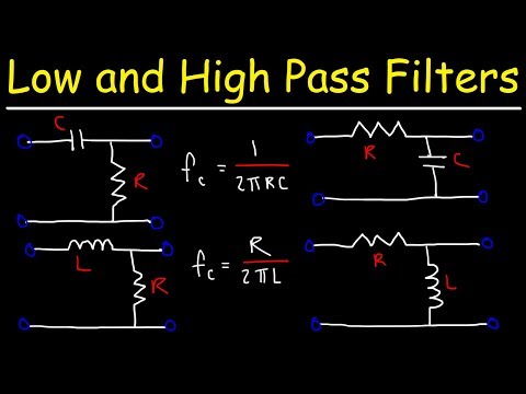
How High Pass Filters Work using a Resistor and Capacitor (RC)

Показать описание
I explain how high-pass RC filters work using the falstad circuit simulator and a circuit which is similar to the one used with the low pass filters in a previous video.
The simulations include the circuit diagram showing current flow, capacitor operation, time-domain voltage plots at various frequencies, and a frequency response plot.
Below is the text of the code I used in Falstad:
$ 1 0.000005 14.235633750745258 55 5 50 5e-11
v 176 256 176 80 0 2 85 5 0 0 0.5
r 176 80 336 80 0 187
c 336 80 336 256 0 0.000009999999999999999 -4.2244607677073445 0.001
w 176 256 336 256 0
o 0 16 0 x81016 20 0.2 0 14 2.5 0 1 3 0.05 0 2 3 0.05 0 1 3 0.05 0 2 3 0.05 0 2 3 0.05 0 1 3 0.05 0 2 3 0.05 0 1 3 0.05 0 2 3 0.05 0 1 0 2.5 0 1 3 0.05 0 2 0 2.5 0 2 3 0.05 0
38 2 F1 0 0.000001 0.000101 -1 Capacitance
 0:18:28
Low Pass Filters and High Pass Filters - RC and RL Circuits
 0:09:55
How High Pass Filters Work using a Resistor and Capacitor (RC)
 0:04:58
High Pass Filters: THE MOST COMMON TOOL IN AUDIO PRODUCTION
 0:01:25
Low pass, High pass, Band pass and Band stop filters explained
 0:00:15
high-pass vs low-pass
 0:13:23
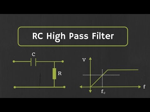
RC High Pass Filter Explained
 0:00:45
Why High-Pass Filters Are Ruining Your Mix
 0:11:35
Low Pass Filters & High Pass Filters : Data Science Concepts
 0:10:33
4G & 5G Network Section Me kon kon se Components or ic hote hai
 0:05:33
RC High Pass Filter Explained | Passive filter | Electrical Engineering
 0:06:55
The Basics of Audio Filters
 0:00:09
How active High pass filter work in electronics circuit
 0:08:37
How Low Pass Filters Work
 0:15:17
Low-pass and High-pass Filters (Explanation and Examples)
 0:00:19
Passive High Pass Filter || Electronics is Powerful Type Yes If You Are Agree
 0:04:34
What Does The HPF (High Pass Filter) Button Do? Audio Mixer Setup
 0:13:36
High Pass Filter - Simple example ep2
 0:00:33
Filter Types Explained In 30 Seconds
 0:00:12
How passive high pass filter work in electronics circuit
 0:03:08
What are High Pass and Low Pass filters in Ultrasonic Testing?
 0:13:32
High Pass Filter - Brain Waves.avi
 0:00:30
Speaker bass and pass filter#shorts
 0:00:27
RC Low Pass Filter #electronics
 0:05:51
Passive RC high pass filter tutorial!
Комментарии