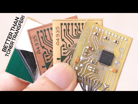
Easy Vias on Home PCBs

preview_player
Показать описание
A whole bunch of tips for dealing with vias on home made PCBs.

For more information on how to make home made PCBs, see this video:
Рекомендации по теме
Комментарии
Автор

Keep them coming Robin! I tried scratch milling on my cheap 1610 mill and it did much better than the engraving bits ever could.

xorfive
Автор

I like your jig for stripping long lengths of wire - I'll give that a try. I do a similar thing to make many pre-cut short lengths by stripping a short piece of multi-strand wire, then cutting the wire to produce a bunch of short pieces that I use for via stuffing. I particularly like your tip on the "sewing method".
I have been using "Z" bends for years. It works well as long as the via hole properly matches the wire size with minimal clearance:

1) Hold the board in your hand while loading a short piece of pre-cut wire through a via from the top of the board using tweezers.
2) Bend the top of the wire over the board while still holding the wire with the tweezers.
3) Use your finger on the bottom of the board to bend the bottom of the wire in the opposite direction as the top bend. You don't have to flip the board over, or see what you're doing, just bend it.
4) Keep doing that until all wires are loaded and bent over on top and bottom with no soldering.
5) Place the board on a hard flat surface such as a ceramic tile square.
6) Place a piece of hard flat material, such as a ceramic tile square, on the top of the board and press down to sharpen the bends on top and bottom. This does not provide sharp bends on all of the wires because many via wires stack on top of each other causing variations in height. This is not a problem as it will be corrected later.
7) Use a scalpel to trim the long wire ends off near the edge of all vias on the top and bottom of the board.
8) Forcefully squish the board once more between the two flat surfaces to assure sharp bends on all of the wires.
9) Flux the entire board using good quality electrical flux and solder-coat the whole thing by lightly dragging a wide, solder loaded iron across the entire board. It helps to do this at an angle, letting gravity aid in flowing the solder from top to bottom. If you find you have used too much solder, simply slurp it up near the bottom of the board with solder wick. Solder coat both sides of the board.

The final solder coat solders all of the vias with a single pass, provides a protective solder coating on all of the traces so that the CU does not oxidize, and makes it easier to solder components. I use a water-soluble flux and clean it under running water with a light scouring pad using a very light touch. This provides a very clean looking board with a brushed-metal surface finish.

davidc.
Автор

Thanks a lot for your valuable experimental tips 😇

VikiLab
Автор

Thank you...this video saved me dozens of hours of trial and error. One tip I stumbled upon is if the pcb design can use through-hole components for places that could use a via, then the leads of those through-hole components can be vias...but I don't know how good that is. Also I saw a lot about using copper rivets, but am not sure how compares either.

EricFontaineJazz
Автор

You can use conductive silver paint. Dip a wire in it and then paint the inside of the hole. Most times these vias are not a real connection but have a resistance of around 10 to 100 Ohms.

filmpjeslader
Автор

I don't understand the original problem to use a wire for a via. With 2 layers - how is that hard exactly?

tcurdt
Автор

hello and thank you:) I have one question, what about some component like IC socket have to connect both side, what can we do for this?

hakank
Автор

Nobody in the world had the idea, that you can create a via with a wire . You should apply for a patent and a Nobel prize.

scultzalex
Автор

I buy a thousand 0.4mm copper rivets and... well you know.. rivet.

foxabilo
Автор

how to make via for a single sided zera pcb 👀👄

xtonx-theofficialbeechslay