filmov
tv
Power Electronics - Buck-Boost Converter

Показать описание
Join Dr. Martin Ordonez and instructor Ignacio Galiano Zurbriggen in a lesson on the design and analysis of the buck-boost converter. This video introduces the topology, details the fundamental relationships between its components, and provides a design example.
Script/Visuals: Ettore Scabeni Glitz
Narration: Ignacio Galiano Zurbriggen
Production: Martin Ordonez
Audio/Video Editing: Gregor Morrison
Music: Back to the Ocean - Jesiah
Photo Credits: UBC Hover Collective, Drew Hays
Script/Visuals: Ettore Scabeni Glitz
Narration: Ignacio Galiano Zurbriggen
Production: Martin Ordonez
Audio/Video Editing: Gregor Morrison
Music: Back to the Ocean - Jesiah
Photo Credits: UBC Hover Collective, Drew Hays
 0:15:17
Power Electronics - Buck-Boost Converter
 0:07:25
Buck-Boost Converter Operation and Voltage Equation
 0:19:32
Buck boost converter (Basics, Circuit, Working, Waveforms, Parameters & Applications) Explained
 0:14:00
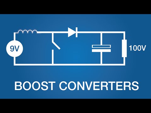
Boost Converters and Buck Converters: Power Electronics
 0:09:39
How does a Buck Boost converter work? Buck-Boost converter Working Explained
 0:11:41
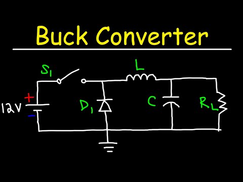
Buck Converter
 0:10:05
Boost Converters - DC to DC Step Up Voltage Circuits
 0:06:43
How Boost Converters Work (DC-DC Step-Up) - Electronics Intermediate 1
 0:00:07
NDUB22TA 2A DC 3V-23V to DC 3.3V 4.2V 5V 6V 10V 12V DC-DC 4-Switch Buck-Boost Converter module
 0:18:48
Lec 26 Understand Buck Boost Converter in 15 Minutes
 0:09:54
How does Buck Converter work? | DC-DC Converter - 1
 0:14:11
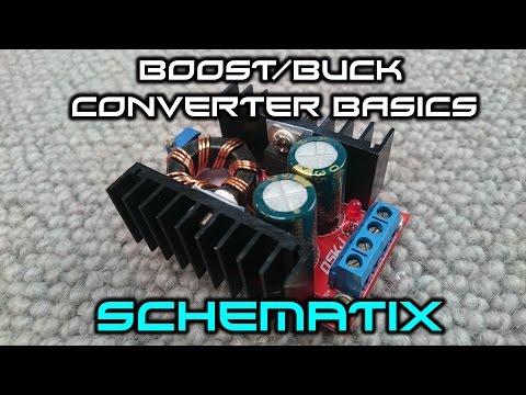
What You Need To Know Before Buying A Boost/Buck Converter
 0:00:56
LM2596 DC to DC Buck Converter Adjustable Step down power supply module
 0:12:51
⚡ DC-DC Buck-Boost Converter Design 🔋 Power Electronics Calculations & MATLAB/Simulink
 0:14:37
Buck Converter (Basics, Circuit, Working, Waveforms, Parameters, Uses & Applications) Explained
 0:00:18
XYS3580 DC-DC ADJUSTABLE BUCK BOOST CONVERTER 5A POWER MODULE #voltageregulation #powersupply
 0:06:44
DIY Buck/Boost Converter (Flyback) || How to step up/down DC voltage efficiently
 0:15:14
Buck-Boost Converter | Power Electronics | GATE (EE)
 0:00:15
300W 20A DC-DC Buck Converter Step Down Module/ Step Down Voltage Module
 0:21:57
Power Electronics - Buck Converter Design Example - Part 1
 0:10:19
Buck Boost Converter Output Voltage Derivation in Power Electronics by Engineering Funda
 0:19:16
Power Electronics Inverting Buck Boost Converter
 0:01:59
ROHM's New Buck-Boost DC/DC Converter Achieves Breakthrough Power Savings
 0:00:46
DC Buck Boost Converter: battery charger #charger #electronics #stepdown
Комментарии