filmov
tv
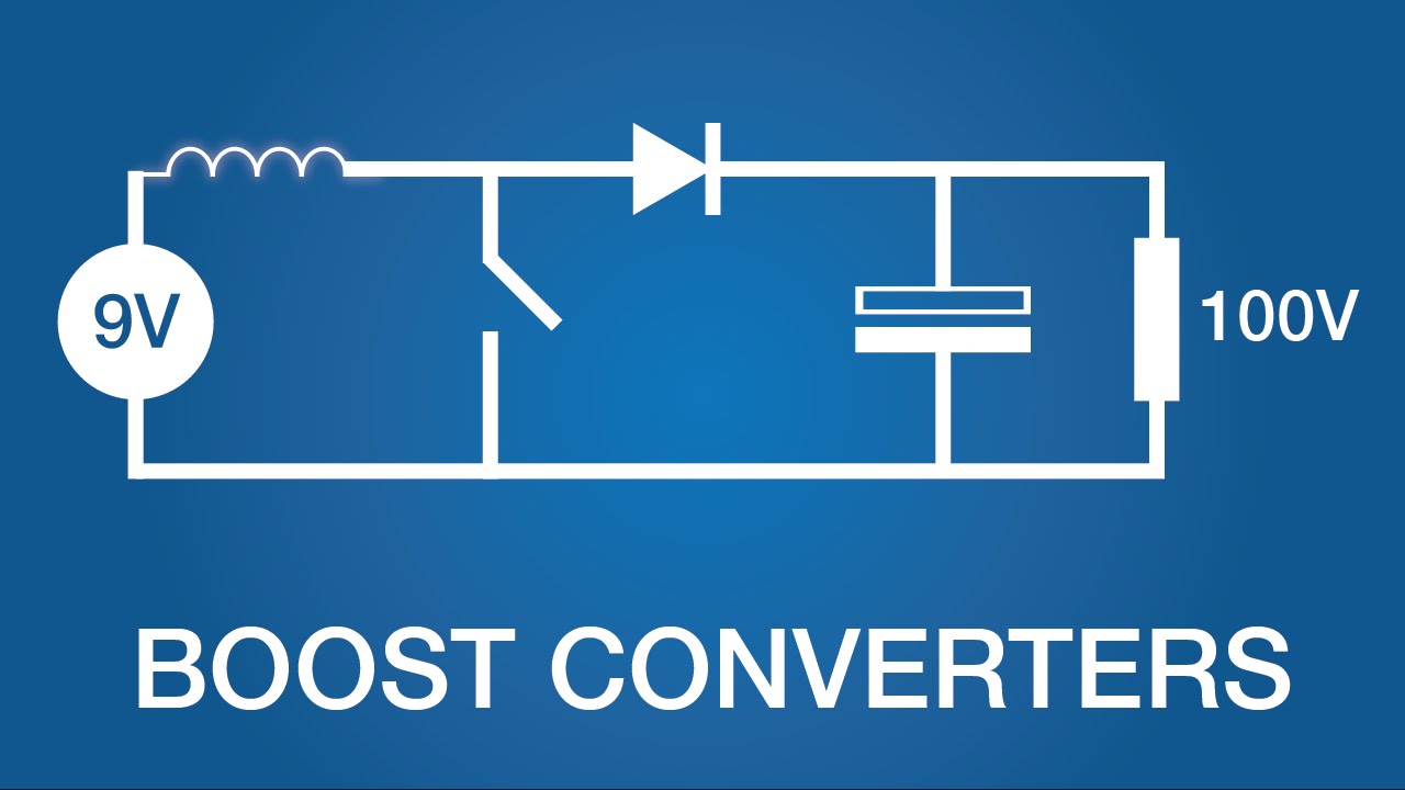
How Boost Converters Work (DC-DC Step-Up) - Electronics Intermediate 1
Показать описание
 0:06:43
How Boost Converters Work (DC-DC Step-Up) - Electronics Intermediate 1
 0:10:05
Boost Converters - DC to DC Step Up Voltage Circuits
 0:06:01
How does Boost and Buck - Boost Converter work? | DC-DC Converter - 2
 0:09:39
How does a Buck Boost converter work? Buck-Boost converter Working Explained
 0:14:00
Boost Converters and Buck Converters: Power Electronics
 0:09:54
How does Buck Converter work? | DC-DC Converter - 1
 0:06:06
DC-DC Boost converter tutorial
 0:05:41
DIY Boost Converter || How to step up DC voltage efficiently
 0:07:44
How to wire a 36v-72v DC-DC Stepdown Converter on 36v 48v 60v 72v Battery for your 12v accessories!
 0:03:16
How a boost converter circuit works
 0:10:36
Boost Converter (Basics, Circuit, Working, Waveforms, Parameters, Uses & Applications) Explained
 0:07:25
Working of a Boost Converter
 0:11:41
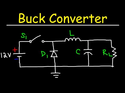
Buck Converter
 0:06:44
DIY Buck/Boost Converter (Flyback) || How to step up/down DC voltage efficiently
 0:07:25
Buck-Boost Converter Operation and Voltage Equation
 0:09:59
Boost Converter Operation and Voltage Equation
 0:03:42
Basic Principle of DC DC Converter - DC DC Converter - Power Electronics
 0:16:13
Boost converter efficiency - worth it? Part 1
 0:14:11
What You Need To Know Before Buying A Boost/Buck Converter
 0:04:02
How Does a Buck-Boost Converter Work? (With Animation)
 0:10:57
The Most Versatile Voltage Converter you never heard of! The (S)EPIC Converter
 0:11:16
Is this the BEST Voltage Converter? Trying to build a Synchronous Converter!
 0:15:38
🔥 Unleash LIMITLESS Power with Parallel DC-DC Boost Converter!⚡
 0:05:40
High Power dc to dc boost 1200W // Simple 5v to 73v DC 1000W DC Motor Run With 3V Battery
Комментарии