filmov
tv
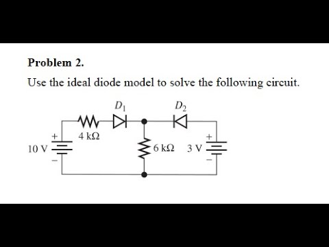
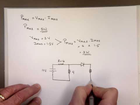
Solving Diode Circuits | Basic Electronics

Показать описание
If you want more videos on basic electronics, subscribe to the CircuitBread channel!
Table of Contents:
0:00 Introduction
0:14 What is the quiescent point, or the q-point, of a diode?
0:36 Load Line Analysis for solving circuits with diodes in them
1:15 Math model for diode circuit
2:18 Ideal diode circuit analysis with the four steps
8:39 Constant voltage drop diode example
14:15 Review of the four methods and four steps
CircuitBread is joining the fight to help people more easily learn about and use electronics. With an ever-growing array of equations, tools, and tutorials, we're striving for the best ways to make electronics and electrical engineering topics more accessible to everyone.
Connect with CircuitBread:
 0:27:04
How To Solve Diode Circuit Problems In Series and Parallel Using Ohm's Law and KVL
 0:15:15
Solving Diode Circuits | Basic Electronics
 0:06:11
use the ideal diode model to find the currents through both the diodes assume diodes are ideal
 0:18:27
How to Solve the Diode Circuits (Explained with Examples)
 0:02:56
Tricky Diode Forward Reverse Bias Circuits. Part 1
 0:12:17
What Is a Diode?
 0:04:01
Diode Circuits Solved Problem | Quiz # 40
 0:05:22
Diode Circuit Solved Problem | Quiz # 55
 1:46:51
Diode circuit formulation analysis for LC load
 0:13:40
DIODES! All Sorts of Them and How They Work (ElectroBOOM101-010)
 0:21:29
Ideal Diodes
 0:11:32
Diodes Explained - The basics how diodes work working principle pn junction
 0:08:43
Introduction to Basic Diode Circuit
 0:08:39
L4 1 4Ideal Diode Conducting or Not Part 1
![[6b] How to](https://i.ytimg.com/vi/bVPt-3pF9-E/hqdefault.jpg) 0:26:03
0:26:03
[6b] How to use the iterative and graphical methods to solve diode circuits
 0:05:01
How To Solve Diode Circuit Problems:01
 0:05:50
Diode Circuits Solved Problems | Quiz # 298
 0:17:49
Clipper Circuits
 0:02:10
Series Diode Circuit Solution (Boylestad Problem 7 b)
 0:04:21
Electrical Engineering: Ch 3: Circuit Analysis (34 of 37) Solving Basic Transistor Circuit (MESH) 1
 0:03:07
Series Diode Circuit Solution (Boylestad Example 2 8)
 0:05:34
Diode Circuit Solved Problem | Quiz # 360
 0:03:41
Diode Circuits Solved Example | Quiz # 244
 0:11:10
Zener Diodes
Комментарии