filmov
tv
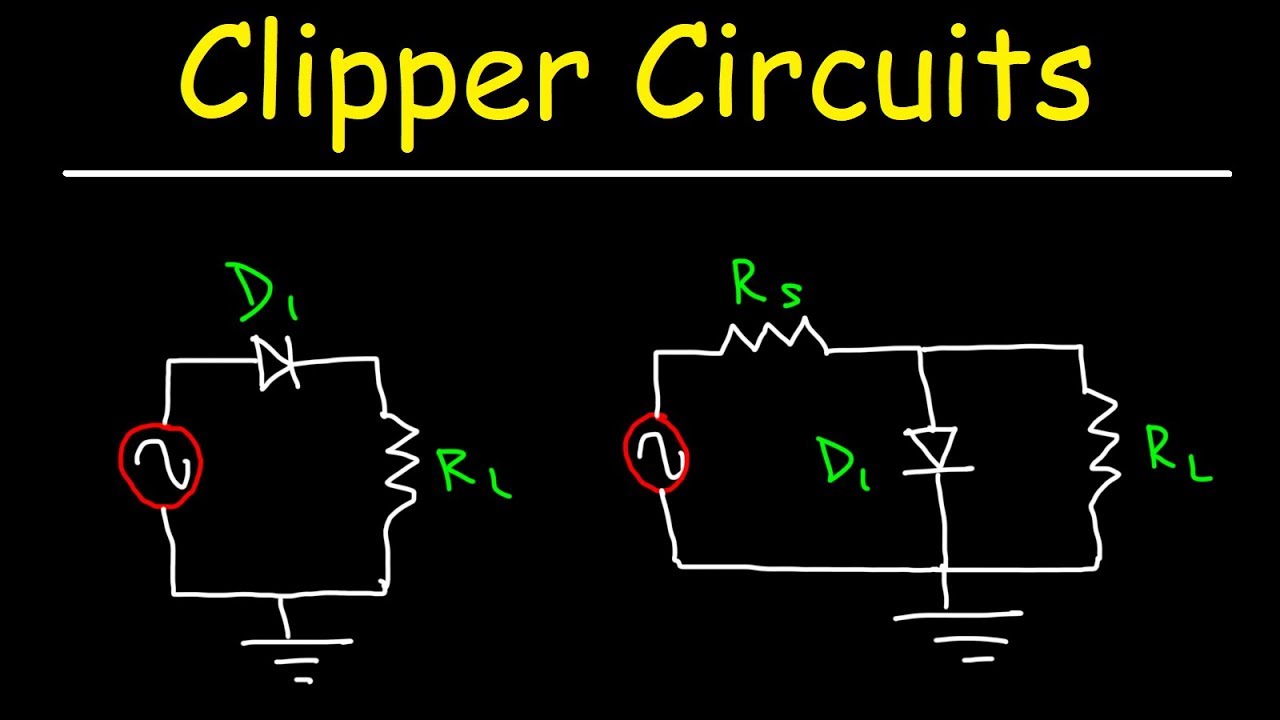
Clipper Circuits
Показать описание
This electronics video tutorial provides a basic introduction into clipper circuits. This includes the positive and negative series clipper circuits as well as the parallel or shunt clipper circuits using diodes, resistors, and even zener diodes.
What Is a Diode?
How To Solve Diode Circuit Problems:
Diode Logic Gates - OR, NOR, AND, & NAND:
Clamper Circuits:
Half-Wave Rectifiers:
__________________________________
Full-Wave Rectifiers:
Full-Wave Bridge Rectifiers:
220V AC to 12V DC Converter:
Capacitor Voltage Booster Circuit:
Half Wave Voltage Doubler Circuit:
Full Wave Voltage Doubler Circuit:
__________________________________
Voltage Multiplier Circuit:
Light Emitting Diodes:
Power Dissipation In LEDs & Diodes:
Final Exams and Video Playlists:
Full-Length Videos and Worksheets:
 0:17:49
Clipper Circuits
 0:17:17
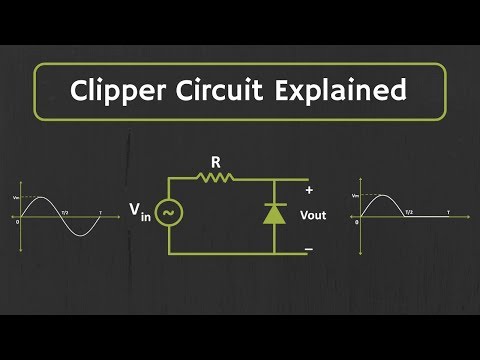
Clipper Circuit Explained (with Solved Examples)
 0:09:45
Using Diodes as Clippers or Clampers | Intermediate Electronics
 0:12:50
Clipper Circuits
 0:16:51
Clipper Circuits | Diode | Diode theory & applications |Basics Electronics
 0:14:21
What are Clipper Circuits? Series and parallel clipper circuits
 0:08:34
Clipper circuit example 1
 0:14:03
Active Clipper Circuit (Clipper Circuit using op-amp) Explained
 0:08:45
Clipper Circuits (Basics, Types, Working & Waveforms) Explained
 0:13:02
Biased Parallel Clippers || EDC 2.9(4)(English)(Boylestad)
 0:01:19
Clipper Circuit | Its types | Applications
 0:05:57
Clipper circuits trick (SOLVE in less than 30 sec )
 0:05:51
clipper circuits | introduction |
 0:07:13
Biased Clippers, Series Negative Clipper with Positive Bias - Rectifier & Filter - Basic Electro...
 0:11:59
Series Clipper || End Ch Q 2.33 & 2.34 || EDC 2.4(2)(English)(Boylestad)
 0:06:30
Introduction to Clipper circuits | Positive and Negative Clipper circuits working principle (bangla)
 0:17:58
CLIPPER CIRCUIT
 0:10:37
OPAMP CLIPPPER - Positive, Negative Opamp Clipper - Circuit, Working, waveforms
 0:03:29
What is Clipper circuit and its types in tamil
 0:09:56
Clipper Circuits using OpAmp | Positive Clipper Circuit | Negative Clipper Circuit
 0:12:46
clipper
 1:22:24
Clippers and Clampers (Electronics 1)
 0:29:42
1.10 Diode Clipper Circuits || Types of Clippers(complete) || Trick to draw output waveforms (Hindi)
 0:36:47
Clippers - 1 | Diode Circuits | Lec 8 | Analog Electronics | GATE 2021 Exam
Комментарии