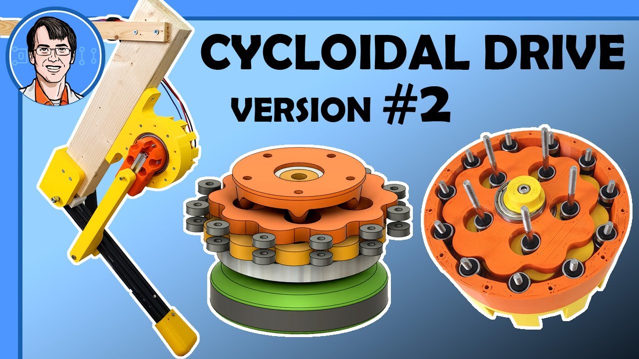
3D Printed Cycloidal Drive V2 - Much Better!

preview_player
Показать описание

In my previous video I built a 3D Printed Cycloidal Drive which was relatively successful, although the cam snapped off under load and it vibrated a lot. This time I've balanced the drive by using two cycloidal discs 180' out of phase with each other. I've also made the cam shaft much thicker and robust by screwing an M4 bolt through the middle of it. This time it's much tougher, although we still need to do a lot of testing.

You can support me on Patreon or buy my Merchandise:
***************************
***************************

Affiliate links - I will get some money of you use them to sign up or buy something:
***************************
***************************

Other socials:
***************************
***************************

Huge thanks to my Patrons, without whom my standard of living would drastically decline. Like, inside out-Farm Foods bag decline. Plus a very special shoutout to Lulzbot, Inc who keep me in LulzBot 3D printers and support me via Patreon.

HARDWARE/SOFTWARE

Below you can also find a lot of the typical tools, equipment and supplies used in my projects:

XROBOTS

Former toy designer, current YouTube maker and general robotics, electrical and mechanical engineer, I’m a fan of doing it yourself and innovation by trial and error. My channel is where I share some of my useful and not-so-useful inventions, designs and maker advice. Iron Man is my go-to cosplay, and 3D printing can solve most issues - broken bolts, missing parts, world hunger, you name it.

XRobots is the community around my content where you can get in touch, share tips and advice, and more build FAQs, schematics and designs are also available.
Рекомендации по теме
Комментарии
Автор

James: "I made a leg that hops to test shock loading."
Meanwhile the neighbors: 😳

freescape
Автор

Love the fact you're exploring cycloidal drives, and I mentioned it in the previous video and I'll mention it again. The gear you have is not a proper cycloid, if it was the bearings around the perimiter would be unnessecary because there should be pure rolling contact between the cycloidal gear and a circular pattern of pins to begin with (i.e. those bearings shouldn't be turning at all). This would let you shrink the size of the thing down, save weight with all the bearings gone and make it cheaper.

Second, you may or may not want to look into this, you can have the outer pins run free, if you fix/anchor the center pins so they don't spin. This might be handy since it moves the output to the outside perimeter. This means you can have the output supported between both ends, rather than cantilevered off the end of the gearbox which I think(?) you mentioned was a bit of an issues with the last design. Paul Gould here on youtube has some designs/videos with this configuration.

H...
Автор

“They’re actually slightly out of phase with each other, by 180°” 😂

bergamt
Автор

That's amazing. There is something really statisfying about seeing precision mechanical prints that work.

memejeff
Автор

I mentioned this in the last video, but there's a variant where the outer housing rotates and the cycloidal disk(s) only wobble (but don't rotate). Since this is intended to be used as a shoulder or leg joint you would be able to print the armature and the outer housing as a single piece. This would seem to have some benefits in weight, overall size, and reduced side loading of the bearings in the whole leg.

Also It looks like you have some space between your cycloidal gear and your bearing surfaces (both inner and outer), which is almost inevitable with 3d printed parts. In a perfect world the cycloid would touch every bearing at all times, and would not have any slip contact with the bearings (which then wouldn't turn). In the real world only a few points will contact at any one position, and you'll see some slip contact with the bearings (which is why they are turning slightly). If you continue using the bearings, consider a compliant membrane (rubber bands?) around the bearings. This will probably quiet the mechanism significantly as well as ensuring all the bearings share the forces, instead of one or two at a time.

speedbump
Автор

Ah yes, my life savings worth of bearings

angzarr
Автор

Those spacers need to be printed in red. Ask Ivan Miranda. He knows.

ifitsrusteditsmine
Автор

@ 6:04 - Every tool is a hammer ~Adam Savage

iamkian
Автор

That looks very nice. You could concider brass inserts insted of roller bearings. Friction will be just bit bigger but you can significantly reduce diameter and mass of drive. (estim 50%). As well just as recomendation for knee joint to use smaller motor and drive as torqe will be much smaller on it. so again you can save some mass.

mariuszhoscio
Автор

I just found your channel yesterday from the Cycloidal Drive v1 video and subscribed. Needless to say, I am thrilled with your timing.

AUser-
Автор

have you thought about using a single cycloid with an off-center mass to counteract the vibrations, i have some ideas to make it pretty precise, also please look at the comment that suggests to use mathematically calculated cycloids that wouldn't slip on the exterior and probably could work witout the external rods with bearings or spacers, it would really save lots of weight and would be an interesting development, i think that mostly on the knee joint, witch will be a moving mass, the weight of the assembly w, ould be strictly related to the mobility of open-dog, i really believe in the project

pietrom
Автор

A backdrivable £50 20Nm 200g 200W actuator would change the world of dynamic jumping robots. I'm not convinced it would be possible with anything less than 50:1 reduction. This means you 'only' need 10A at 20V and a 200kv motor delivering 0.4N at 5000rpm.
The "Open Dynamic Robot Initiative" (website on github) is also quite impressive. They save weight by integrating the reduction into the leg instead of a separate actuator. 12 x 1100g is quite a weight budget before you even start on the body.

luke.perkin.online
Автор

You might have seen this before but the VESCs are able to connect to hall effect sensors for positional accuracy if your motor has them. It solves (or reduces) lots of the issues with stall torque and can safely dump a lot more current in at low speeds

cian.horgan
Автор

I Seriously think this is one of the most underrated stuff in youtube.

Been following since you were 23k subs James and you were doing the First Iron man stuff. Such a great channel. Thanks for existing and creating all of these videos.

maatheovallejo
Автор

I am a homeschooler, but I have a coop on Tuesdays that starts early. Every Tuesday morning, I make it a priority to watch your new videos before I leave for school! Thanks!

nickbaddorf
Автор

All this professional production and the man is using a screwdriver as a hammer

UltimateSugar
Автор

I use VESC with hall sensors or a AS5047D encoders all the time.
With an AS5047D the VESC supports position control, too.

countZ
Автор

AGS Door Ease Lube Stick is a very effective lubricant for plastic-on-plastic parts. Just apply like a crayon onto the 3d printed parts and exercise the joint. In a few motions it is super slick without the liquid residue. I simply don't use oils or greases any more on 3d printed parts.

keg
Автор

An simple trick to increase layer line strength is to just print at an angle. Even a slight angle will help. With some of these parts that are held on the inside of a bearing, you could put a flat spot on the OD of the part and print it on its side as to not use any support material.

Another easy trick is with counter sink screws. If you use a hand drill to spin the screw fast in the hole before assembly, you can friction form the counter sink to the shape of the screw. This not only more evenly distributes the force of the screw head to the plastic but also bonds the layers in the countersink together better. Also, this helps when you don't know the dimensions of the screw head. (some) Wood screws have a compound angle on the head and instead of trying to model it perfectly, get it close and melt it with friction the rest of the way.

Griffin
Автор

Hey James! Loved the video. Just a thought for the final build, you should look into precision shoulder bolts... They have a precisely ground diameter and a threaded section on the end. Should work really well for a bearing fit without much redesign. They're not too expensive either. Cheers!

devinmoodley
visit shbcf.ru