filmov
tv
What is Noise Figure & How to Measure It – What the RF (S01E05)
Показать описание
Learn how to see low level signals by adjusting this setting.
Learn more in the Spectrum Analysis Basics application note ↓
Like our Facebook page for more exciting RF content:
Check out our blog:
WTRF Eps. 4:
Learn more about using oscilloscopes:
Check out the EEs Talk Tech electrical engineering podcast:
Like our digital counterpart’s Facebook page:
Twitter: @DanielBogdanoff
(The Keysight X-Series PXA 3 Hz - 50 GHz)
Transcript:
When working on your product’s design you’ll often want to optimize the sensitivity of your receiver. That’s where being able to characterize and improve your system’s noise figure becomes one of the important factors to consider.
What’s up everyone!! The name is Nick Ben and I’m an engineer here at Keysight… and welcome to the 5th episode of ‘What the RF!’
In today’s episode we’ll be discussing noise figure, including what it is and how to measure it.
Noise figure is one of the most important design considerations in the sense that it is a very efficient way to evaluate the performance of your device.. You can make noise figure measurements on complete systems or components. These include almost all multi-port devices from passive devices to active devices. Let's learn more about it.
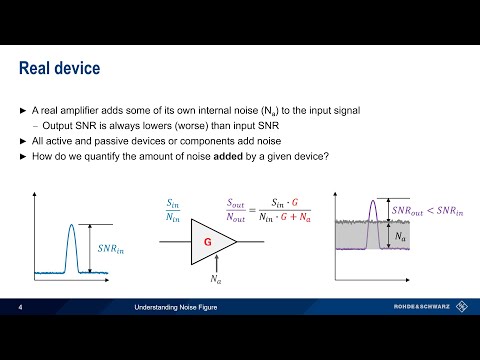
Noise figure is the degradation of the SNR as a signal passes through a system or device. Noise figure tells us the relative amount of noise being added to the signal.
In our case, the device is this low noise amplifier.
To calculate noise figure we determine the ratio of the respective signal-to-noise power ratios at the input and output of the device. Device must be at a reference room temperature of 290 degrees kelvin.
Noise contribution in electronics is also caused by thermal agitation of electrons – or thermal noise. 290 kelvin was adopted by institutions as the standard temperature for determining noise figure.
The noise figure value is a number expressed in dB and indicates the performance of a device’s internal components like this amplifier.
A low noise figure is good and high noise figure is bad.
We see an example of a signal at an amplifier’s input in (a) and at its output in (b).
As you can see on the right, the noise level rises more than signal level due to the noise added by the amplifier’s circuits. This is the amplifier’s noise figure value.
By knowing your device’s noise figure value you can calculate a system’s sensitivity from its bandwidth. Noise figure is a key parameter when handling small signals, and quantifies the network’s added noise.
All you need to characterize your device’s noise figure is a signal analyzer, a noise source to calibrate with, and your device.
For a noise figure measurement there are only 2 main steps you’ll need to follow –
1. Calibrate your test system; and
2. Measure your DUT’s noise figure
Yes, it’s really that simple.
As mentioned earlier in the video, the DUT we’ll be testing is this low noise amplifier, but we’ll first need to calibrate our signal analyzer.
In this first step, we’re calibrating our signal analyzer. All we’ll need is a noise source and a signal analyzer.
Switching over to the noise figure application on our signal analyzer, we see that our signal analyzer is uncalibrated, and we know this by the cal-state indicated at the top right hand corner.
So let’s go ahead and calibrate this. Going into the measurement setup menu, we press the DUT setup & the calibration button.
Today, we're just going to set up one DUT - this amplifier - which has a frequency range from 10 MHz to 1 GHz. But, I'm going to set the maximum frequency range parameters for the test to 3 GHz. By doing this, we'll be able to see the amplifier's performance roll off as we scan past its operating range. You can see where you would need to spec the amplifier.
Now it’s time to measure the noise figure of our amplifier. To do so, we just have to remove the noise source from the front end of the analyzer and in its place connect the DUT, with the noise source at the input of the DUT.
Looking at the graph here we see that our noise figure is a little above 6 dB and the gain is about ~20 dB which isn’t terrible … but ideally we would like to see our noise figure be under 3 dB.
Noise figure is an easy measurement for characterizing a device’s signal-to-noise ratio (SNR) as a signal passes through a system or device.
#noisefigure #noisefiguremeasurement #signalanalyzer #spectrumanalyzer #rfengineering #signalsource #signalgenerator #keysight #rfengineering
Learn more in the Spectrum Analysis Basics application note ↓
Like our Facebook page for more exciting RF content:
Check out our blog:
WTRF Eps. 4:
Learn more about using oscilloscopes:
Check out the EEs Talk Tech electrical engineering podcast:
Like our digital counterpart’s Facebook page:
Twitter: @DanielBogdanoff
(The Keysight X-Series PXA 3 Hz - 50 GHz)
Transcript:
When working on your product’s design you’ll often want to optimize the sensitivity of your receiver. That’s where being able to characterize and improve your system’s noise figure becomes one of the important factors to consider.
What’s up everyone!! The name is Nick Ben and I’m an engineer here at Keysight… and welcome to the 5th episode of ‘What the RF!’
In today’s episode we’ll be discussing noise figure, including what it is and how to measure it.
Noise figure is one of the most important design considerations in the sense that it is a very efficient way to evaluate the performance of your device.. You can make noise figure measurements on complete systems or components. These include almost all multi-port devices from passive devices to active devices. Let's learn more about it.
Noise figure is the degradation of the SNR as a signal passes through a system or device. Noise figure tells us the relative amount of noise being added to the signal.
In our case, the device is this low noise amplifier.
To calculate noise figure we determine the ratio of the respective signal-to-noise power ratios at the input and output of the device. Device must be at a reference room temperature of 290 degrees kelvin.
Noise contribution in electronics is also caused by thermal agitation of electrons – or thermal noise. 290 kelvin was adopted by institutions as the standard temperature for determining noise figure.
The noise figure value is a number expressed in dB and indicates the performance of a device’s internal components like this amplifier.
A low noise figure is good and high noise figure is bad.
We see an example of a signal at an amplifier’s input in (a) and at its output in (b).
As you can see on the right, the noise level rises more than signal level due to the noise added by the amplifier’s circuits. This is the amplifier’s noise figure value.
By knowing your device’s noise figure value you can calculate a system’s sensitivity from its bandwidth. Noise figure is a key parameter when handling small signals, and quantifies the network’s added noise.
All you need to characterize your device’s noise figure is a signal analyzer, a noise source to calibrate with, and your device.
For a noise figure measurement there are only 2 main steps you’ll need to follow –
1. Calibrate your test system; and
2. Measure your DUT’s noise figure
Yes, it’s really that simple.
As mentioned earlier in the video, the DUT we’ll be testing is this low noise amplifier, but we’ll first need to calibrate our signal analyzer.
In this first step, we’re calibrating our signal analyzer. All we’ll need is a noise source and a signal analyzer.
Switching over to the noise figure application on our signal analyzer, we see that our signal analyzer is uncalibrated, and we know this by the cal-state indicated at the top right hand corner.
So let’s go ahead and calibrate this. Going into the measurement setup menu, we press the DUT setup & the calibration button.
Today, we're just going to set up one DUT - this amplifier - which has a frequency range from 10 MHz to 1 GHz. But, I'm going to set the maximum frequency range parameters for the test to 3 GHz. By doing this, we'll be able to see the amplifier's performance roll off as we scan past its operating range. You can see where you would need to spec the amplifier.
Now it’s time to measure the noise figure of our amplifier. To do so, we just have to remove the noise source from the front end of the analyzer and in its place connect the DUT, with the noise source at the input of the DUT.
Looking at the graph here we see that our noise figure is a little above 6 dB and the gain is about ~20 dB which isn’t terrible … but ideally we would like to see our noise figure be under 3 dB.
Noise figure is an easy measurement for characterizing a device’s signal-to-noise ratio (SNR) as a signal passes through a system or device.
#noisefigure #noisefiguremeasurement #signalanalyzer #spectrumanalyzer #rfengineering #signalsource #signalgenerator #keysight #rfengineering
 0:09:01
What is Noise Figure & How to Measure It – What the RF (S01E05)
 0:14:53
Understanding Spectrum Analyzers – Noise Figure
 0:04:55
Noise Figure (Basics, Definition, Formula, Calculation & Units) Explained in Analog Communicatio...
 0:25:53
Signal to Noise Ratio, Noise Temperature and Noise Figure
 0:10:36
Module 21: Noise Figure
 0:10:07
Noise Figure
 0:13:14
Noise figure | Introduction | Radar Systems | Lec-60
 0:03:20
R&S FSW Signal and Spectrum Analyzer, Measuring noise figure and gain
 0:08:24
Noise Figure Measurement [Y Factor Method]
 0:09:03
#957 Gain and Noise Figure in transistors
 0:11:40
Noise Figure Measurement [Gain Method]
 0:12:29
Measuring Noise Figure using a Spectrum Analyzer - The Gain Method
 0:13:47
SNR I Noise Figure | Noise Temperature I Amplifier Noise | Friss Formula I L-1 Noise | GATE ESE NET
 0:09:32
Noise Factor-Basics of Communication Systems - Communication Engineering
 0:13:37
Go Figure : Noise Figure (#761)
 0:08:19
Introduction to Noise Figure with Example | COM SYS | R K Classes | Hindi | Join Telegram | Lec-115
 0:08:04
Equivalent Noise Figure and Noise Temperature in Cascaded system in Analog Communication
 0:02:23
Inside Wireless: Noise Floor
 0:03:59
Setting up Noise Figure Measurement for a Simple Converter
 0:02:51
Noise Figure - Amplifier Fundamentals - Analog & Mixed VLSI Design
 0:07:43
Keysight PNA-X Network Analyzer’s Accurate Noise Figure Measurement
 0:22:07
25. Noise Factor Examples
 0:08:35
Noise Figure of an ideal amplifier
 0:07:00
Calibrating a Noise Figure Measurement with a Power Meter
Комментарии