filmov
tv
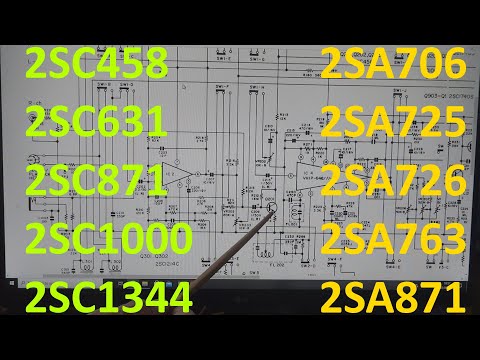
#957 Gain and Noise Figure in transistors

Показать описание
Episode 957
I look as some circuits from the ICOM radio. This is the microphone preamp
I look as some circuits from the ICOM radio. This is the microphone preamp
 0:09:03
#957 Gain and Noise Figure in transistors
 0:12:29
Measuring Noise Figure using a Spectrum Analyzer - The Gain Method
 0:00:58
Transistor Noise - Collin's Lab Notes #adafruit #collinslabnotes
 0:01:02
How To Find Noise Ratio and Noise Figure For Transistor Amplifier || Solved Problem
 0:00:30
the mountains ehere scp 096 was found.
 0:03:32
How to measure Noise Figure using a Vector Network Analyzer?
 0:07:00
Calibrating a Noise Figure Measurement with a Power Meter
 0:22:44
Op Amps: Noise
 0:01:29
Dying at A-999 In Doors
 0:03:18
Electronics: Understanding Noise Figures for BJT transistor (2 Solutions!!)
 0:24:59
Noise Figure Tutorial, Lecture 66
 0:06:50
Sampling transistor noise to pick the winners for my filter giveaway
 0:16:49
#1563 New fan for Keysight Oscilloscope
 0:05:31
My Singing Monsters In Real Life!
 0:13:35
Amplifier noise principles for practical engineer 1 of 4
 0:31:07
Noise Lecture 3 | Circuit Noise Analysis and Representation, Behzad Razavi
 0:09:52
A transistor-based transimpedance amplifier for the LISA QPRs
 0:07:51
#836 Basics: Transistor (3 of 3)
 0:25:37
#1157 Transistor Current Gain (Beta Hfe)
 0:18:09
Fault Finding Noisy Intermittent Transistors in Amplifier & Receiver. Popping noise, crackle sou...
 0:42:57
How To Replace a Twin Turbo V8 Porsche Cayenne - Swapping our Hydro Locked 957 Engine
 0:01:29
Transistor noise figure in common base / common gate configuration
 0:00:16
Noise maker horn battle on New Year's Eve 2023 #kids #shorts #happynewyear #2023 #toys
 0:07:53
Don't (EVER) Use Engine Oil Flush In Your Car !!
Комментарии