filmov
tv
EEVblog #667 - Agilent 6643A Power Supply Binding Post Hack

Показать описание
Dave shows how to upgrade an Agilent/Keysight 6643A/6642A/6641A system dc power supply to have front panel binding posts.
Sense lines are added to improve the high current accuracy.
EEVblog Amazon Store (Dave gets a cut):
Donations:
Projects:
Electronics Info Wiki:
Sense lines are added to improve the high current accuracy.
EEVblog Amazon Store (Dave gets a cut):
Donations:
Projects:
Electronics Info Wiki:
 0:22:19
EEVblog #667 - Agilent 6643A Power Supply Binding Post Hack
 0:11:47
Lets modify a HP (Agilent) 6643A Power Supply with Front Binding Posts
 0:16:33
EEVblog #166 - HP Agilent E3610A Lab Power Supply
 0:44:39
EEVblog #655 - Auction Score
 0:15:40
Agilent U8001A Teardown
 0:29:18
EEVblog #663 - Compucorp 322G Calculator Teardown
 0:50:43
EEVblog #661 - Mailbag
 0:33:18
EEVblog #814 - Keysight N8762A 600V 5100W PSU Teardown
 0:01:13
#1 Tear Down - Agilent E3634A Power Supply - Beta Test Circuit
 0:30:59
EEVblog #670 - FLIR TG165 Lepton Sensor Followup
 0:18:05
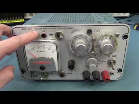
EEVblog #649 - Power Designs 2005 PSU Teardown
 0:03:50
EEVblog #404 - Korad PSU Followup
 0:44:26
EEVblog #680 - Mailbag
 0:00:47
Agilent E3646A, DC Power supply testing, Set B.
 0:12:10
Fonte Agilent... MODIFICAÇÕES
 0:42:44
EEVblog #694 - Mailbag
 0:13:33
Very Heavy HP Power Supply Tear Down
 0:31:05
Extreme PCB Repair, E3611A Power Supply
 0:59:41
EEVblog #439 - Atten PPS3205T-3S Triple Output Power Supply Review
 0:53:39
EEVblog #777 - Keithley 177 Microvolt DMM Repair
 0:32:04
EEVblog #669 - FLIR TG165 Thermal Imager Teardown
 0:20:06
EEVblog #654 - Sydney Maker Faire 2014 Behind The Scenes
 0:29:01
EEVblog #1133 Mailbag Monday
 0:38:39
EEVblog #668 - Mailbag + FLIR TG165
Комментарии