filmov
tv
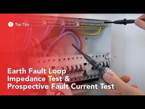
Earth fault loop impedance testing - ZS

Показать описание
Yo!
In this video i run trhough the full process of earth fault loop impeadance testing and about of the theory behind the ZS test.
If you enjoy electrical content please subscribe to the channel and checkout my links below 👇
M Y W E B S I T E ⚡
M Y L O A D O U T 🛠️
B I G B O O T S D I S C O U N T 🥾
U N I L I T E D I S C O U N T 🔦
J O I N T H E C H A N N E L 🤝
I N S T A G R A M 📷
T I K T O K ♪
The works carried out in the video and the opinions shared are my own, and not representative of the associates and companies in the video.
This content is purely for entertainment purposes and is in no way a "how to", tutorial or educational video.
Please consult an electrician when dealing with any electrical installations.
#electricianlife #electrical #electricalengineering
 0:03:52
How to Carry Out Earth Fault Loop Impedance Test - Measuring Zs | PTT
 0:05:32
External Earth Fault Loop Impedance Ze Test - How to Remove Parallel Earth Paths - Live Testing
 0:01:49
Earth Fault Loop Impedance
 0:02:22
Electrical testing LIVE measuring external earth fault loop impedance Ze
 0:03:09
Earth Fault Loop Impedance
 0:15:04
Loop Impedance Testing
 0:16:50
Earth Fault Loop Impedance Test & Prospective Fault Current Test
 0:04:56
Earth loop impedance test, ZE test
 0:04:12
Earth Fault Loop Impedance Test - 3 Lead Low or 2 Lead High - Test Explained
 0:09:32
Earth fault loop impedance testing - ZS
 0:02:20
Earth fault loop impedance test
 0:00:27
Earth fault loop impedance test
 0:05:14
How To Test Earth Fault Loop Impedance (EFLI)
 0:02:03
Fault Loop Impedance Testing
 0:10:42
Loop Impedance Testing | How to check Loop Impedance | Earth Fault Loop Impedance Testing
 0:11:55
LIVE Testing on a 3 Phase Dis-Board - External Earth Fault Loop Impedance Ze, PEFC, PSCC AM2 & A...
 0:01:34
Total Earth Fault Loop Impedance Zs = Ze + R1 + R2 for TN-S and TN-C-S Earthing Arrangements
 0:27:21
Maximum Earth fault loop impedance
 0:04:57
Electrical Capstone Practical Exam. Earth Fault Loop Correct Installation / Fault Finding.
 0:15:46
LOOP IMPEDANCE & PFC – ASSESSMENT TIPS - PROSPECTIVE FAULT CURRENT ZE PSCC ZS – UNDERSTAND THE T...
 0:05:01
How to measure the total Earth Fault Loop Impedance Z(s)?
 0:15:56
Loop Impedance
 0:06:04
EXTERNAL EARTH FAULT LOOP IMPEDANCE - 3 PHASE SUPPLY - AM2S/E
 0:15:14
LOOP IMPEDANCE – WHY IS IT IMPORTANT - Ze and Zs – How does Loop Impedance affect my installation?...
Комментарии