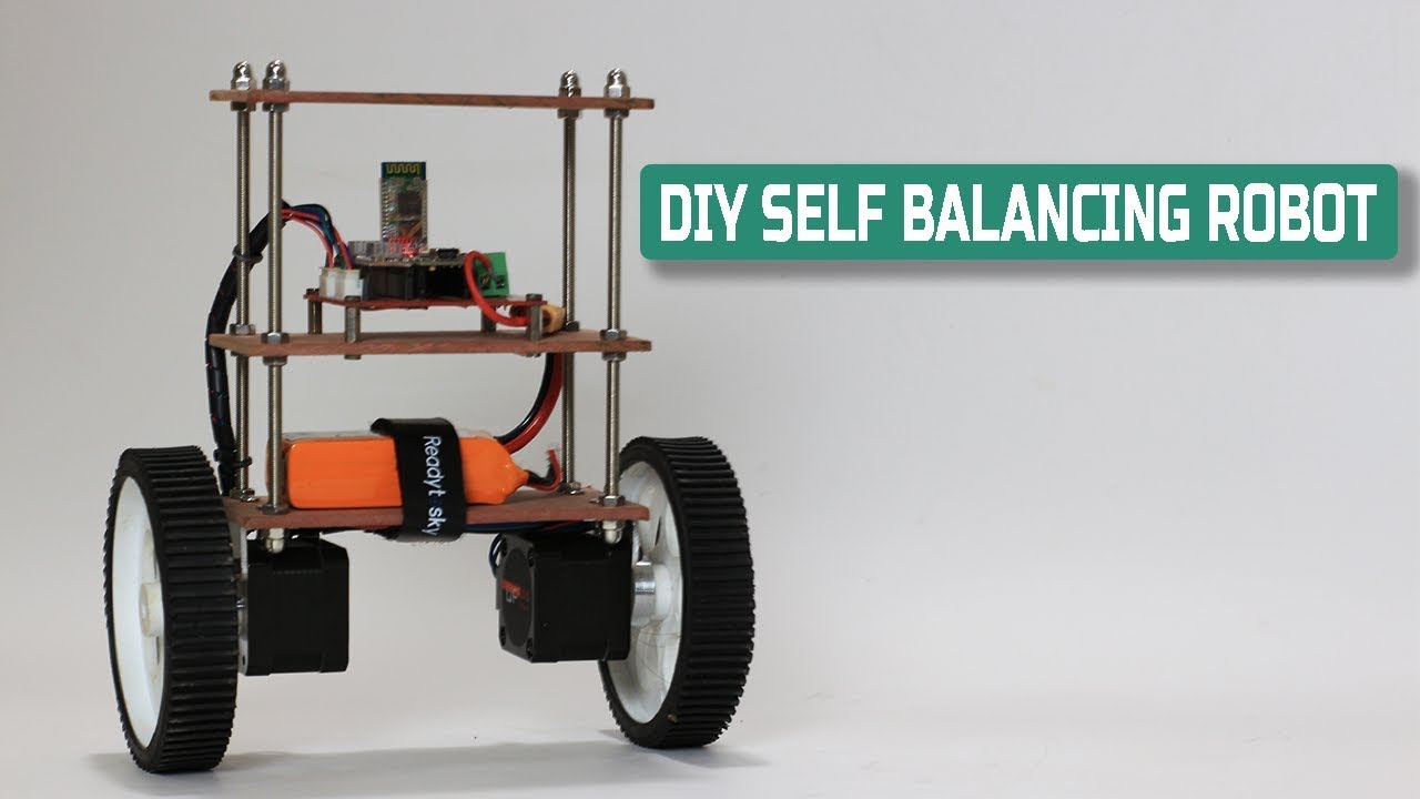
Diy self balancing robot arduino based.

preview_player
Показать описание

Hello friends this post is about DIY self balancing robot in this post I'll show how you can build your own Self balancing robot.
I have use a custom made PCB, Arduno nano, MPU6050, A4988 driver, HC-05 bt module, MDF board and some hardware to build this self balancing robot,
detail material list you can found further in this post.
Balancingwii firmware and EZ-GUI android app is used in this project to control robot via Bluetooth connection.

For Complete project detail, code, circuit drawing visit

Components Required

Arduino Nano..................................1 no.
MPU605 Gyro sensor...................1 no.
Nema 17 Stepper motors.............2 nos.
100mm Wheels................................2 nos.
A4988 Stepper driver IC..............2 nos.
HC-05 Bluetooth module.............1 no.
4mm MDF board.
150mm M5 threaded rods--------4 nos.
some nuts and bolts

Music credit to
Joakim Karud

💻visit for more projects :-

My Gears :-

Рекомендации по теме
Комментарии
Автор

Congrats!! One of the best projects in the web. My graduation project was a self balancing cart. It was 1989. It doesn't work. There were not so many ready made circuits like Arduino. You showed times have changed.

akirahonda
Автор

Finally I managed to successfully implement this robot, congratulations to the author! I had difficulty understanding the PID adjustment, but in the end, after many tests, I realized that it would not be necessary to change any of the data reported (based on the video values) the critical point, in my case, was to leave the resolution of the step in eighth step (only ms1 and ms2 connected in 5V and ms3 floating), with the sixteenth step the robot was able to balance itself but it was not in a fixed position, it made an oscillation amplitude of about 40 cm. It was necessary to change the transmission rate of the HC-05 to 115200 by AT commands, but it was fine. To make the cursor go back to the center in the app: settings => check the "back to MID" fields. Do not forget to use an electrolytic capacitor (100 uF or more) between the Vmot and GND pins of the A4988 driver, unfortunately, during the tests, some were burned because I did not use this capacitor. Any questions I will be happy to help you.

leobrunotronico
Автор

Beautiful project. And one of the benefits I like is, no requirement to 3D print parts ( I don't have one yet but am considering a future purchase). I love how 'clean' this project is as well. Great job.

EngineerNotFound
Автор

Alhumdulilah I am near to complete this project I am very glad and thankfully to the vedio maker, , 😊🥰🥰

afreenkhanawan
Автор

I went to the blog and w3as hoping for a tutorial on the process but unfortunately it was more a tutorial on how to download copy and paste. Wish i could find a real well explained tutorial that doesnt skip the math

EdwinFairchild
Автор

Great job. Thanks a lot for sharing it. I wish next time you make it a way that the robot gets up on its own. I am sure you have the skills to do it. Thanks again

mingosutu
Автор

EZ-GUI is saying no data received when i tried to connect it with HC-05 at baud rate of 115200. and also AUX is showing "not enough information".

mohdaijaz
Автор

One question, how did you make the bluetooth connection with the application work on the hc-05 model (I'm doing the same project, but the bluetooth connection is not working well)

RIVALDIOS
Автор

Really needed this channel. Best reference for arduino projects!

arduinoherman
Автор

Sir kindly clear which maximum android version can support EZ-GUI Ground Station app?

it_world_by_faizan
Автор

Are you meant to see the red lights at 11:26 when you have uploaded the code? Mine didnt do that but arduino ide said it was uploaded. My robot isn't doing anything when I plug its battery in

hiper_tops
Автор

Where to find a mechanical model for the Inverted Pendulum ? what kind of control do you use ? just PID ? do you control engine current or just the tension/PWM ?

Alain_Co
Автор

A small doubt, can we use cnc driver for this project with the same code including a4988.what will be the code changes

sainitinandnikhil
Автор

great work ...i have a question i have the motors rotating in different direction !!
how can I change the direction of the orongue one .. thank's .

samsoft_dz
Автор

Hi,
I'm in the middle of building this robot and I have a question. I'm building without the custom PCB (ie on normal breadboard), so I'm using your diagram. It all seems OK except for one connection. On the top A4988 stepper driver the ground pins are connected through a 1K resistor to the step pin and to D5 on the arduino. This seems wrong - I would have thought that the two ground pins should connect directly to ground, with the step pin connected to D5 and a 1K bridge to ground (ie the same as the bottom A4988 driver). Have I misunderstood the circuit, or is it just a misprint ?

BikermanCoUk
Автор

Is there a difference between using a N20 instead of a N17 stepper motor?

schwups
Автор

Thanks a lot for repeating my project!

mahovvik
Автор

Sir I made the robot as you shown in the video and also make the circuit same as the diagram and put a capacitor of 100uf between vmot and gnd.
But when I place the robot vertically steeper motors are continuously rotating
I also done the calibration and Aux and pid settings.
Please help me to figure out the problem.

saikatdhara
Автор

Fantastic project, and so inspiring. Thumbs Up - for sure.

KiarvaYT
Автор

What about MS1, MS2, MS3 pin of A4988 driver?

Please tell me as soon as possible.
Your PCB sketch and the real PCBs are of different connection with those pins.

diptangshudas
visit shbcf.ru