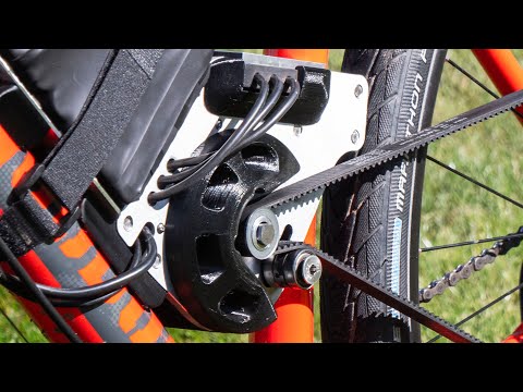
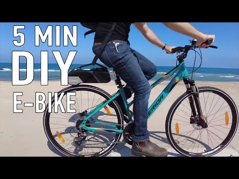
Building an Electric Bike Without Electronics

preview_player
Показать описание


My 3D Printers

----------------------------------------------------------------------------------------------------------------------------------------

My Other Equipment:

----------------------------------------------------------------------------------------------------------------------------------------
#3dprinting #physics #engineering #magnet #electromagnet #science
Рекомендации по теме
Комментарии
Автор

I'm glad to see that you haven't broken the laws of thermodynamics. But at the same time I'm slightly sad you haven't broken the laws of thermodynamics.

mrharvest
Автор

My dad worked in the factory that pioneered reed switches, back in the 60s. He was a toolmaker draughtsman and his input was the part of the machinery that held the reeds in exactly the right position while the glass cooled. A much more tricky operation than it sounds, as the quality control was extreme on those switches, if the gap or alignment was out by just a thou or two, they were rejected. As a result, I had dozens of 'failed' reed switches from his testing, which are actually perfectly good switches and still work today. I don't have many left now, but when my youngest daughter (2nd marriage) was doing a project in primary school, I realised that it was perfect for a reed switch. She was then about the same age as I had been when my dad was running those tests, so that reed switch she used was over 50 years old, and still worked perfectly. Not bad for a reject!

paulhaynes
Автор

You could add a 17v rated zener diode and a power resistor. When voltage goes over 17v it dumps the power into the resistor, heating whatever, instead of blowing up your supercaps and potentially neuter you.

Thingsthatgopew
Автор

This so cool. This could have been half a dozen videos about each component, and I honestly wouldn't be unhappy if you still made those videos. The motor is awesome

Nighthawkinlight
Автор

at 12:30 you missed putting a Mehdi with FULL BRIDGE RECTIFIER 😄

andrew-vlgu
Автор

So, I used to make tungsten contacts for obsolete ignition systems.
You have to silver solder them. A small blowtorch will do it.

As for the sparking. Well, that's exactly what ignition contacts do. If the condenser (capacitor) fails.
You have to have a high rating as peak voltage can be very high, and the value can be trial and error. It has to be matched to the system. Not too big, not too small.

But it eliminates almost all the sparking. Which is all inefficiency as its not just turning off but wasting energy on the plasma.

You may then be able to massively reduce the mass of the moving switch.
Silver solder on the end of the tungsten rod. The cut it off with a grinding disk. Grind and sand back to a nice thin disk. So low mass.
The other contact can be a disk as well then so it has more area to conduct.

The lower mass on the Reed switch will mean it can function at higher frequency.

Madkite
Автор

For those who deal with old cars, your switch is basically called 'points'. You can buy one from car parts stores

henrymach
Автор

13:32 it’s better than free energy, it’s negative cost energy as it is reducing your need to replace break pads 😂

RossGirven
Автор

That microswitch wasn't rated for 15 A :-) that number was just for AC. For DC (your case), it's just 0.6 A.

AC crosses zero so is much easier to disconnect, the arc is self-extinguishing. A DC arc keeps on burning and pitting the contact surface.

iaadsi
Автор

Hey Tom! Awesome build as always! I have a question, wouldn't using a core for your windings significantly amplify the magnetic field and increase the torque, or generated energy? I'm not super familiar with the type of topology you are using, maybe I'm missing something important. Have fun!
[edit] Oh I see you explained why you used this type at 9:05, to remove the force of regular motors against turning when motor is idling. Although I'm not convinced that force exists at higher speeds. I think it is there only when you want to start rotating them. Maybe I should experiment on this a bit...

ElectroBOOM
Автор

I love how you explain everything you make and really make it easy to understand, its awesome

hoodieguy
Автор

I electrified an ordinary bike in about 1975 by using a car heater motor and a car battery under the cross bar. I tried a belt drive to a big pulley (actually just a channel bent into a big circle) on the rear wheel, and also tried a friction drive. Both these worked to some extent, just riding up and down my road. Thank you for the video.

msfkhz
Автор

To further the explanation at the beginning: it's electric, not electronic

BodywiseMustard
Автор

Excellent project! As a very old dude, I am amazed at what we can do with 3-D printing nowadays. In the dark ages, I had to send my drawings down to the workshop and await a much less detailed prototype mechanism to arrive a week or more later. Then I would have to buy the technician a few bottles of beer for prioritising my needs! Thankfully nobody else knew this trick!

TCSC
Автор

There's a German bicycle headlight company called Magnic. What's interesting about their bicycle headlights are that they don't use physical contact between the dynamo, but instead has a rotor with magnets on it that is put in close proximity to the rims of the wheels. The rim rotating past the magnet closest to it on the rotor has a magnetic eddy current induced in the metal of the rim, the eddy current creates a magnetic field, and the magnetic field of the eddy current drags and spins the rotor for the next magnet to do the same thing, etc., spinning the rotor with magnets past some could wire, generating enough power to light some efficient LEDs. Yes, there is some resistive friction between the rim and rotor with the interactions between the magnets and the eddy currents, but it has to be significantly less than those from the much more physical friction of an old-style "bottle generator". I've been interested to see if this could be upscaled enough to charge a cellphone, or power a Bluetooth speaker.

PJ
Автор

Great job, Tom! Small suggestion for whatever it's worth: a tensioner usually does better on the slack-side (bottom side in this configuration) of the belt. The top side is going to almost always be in tension, so it doesn't need a tensioner there. On the bottom side, you can even spring-load it to be an auto-tensioner, but on the top side, you would be fighting the spring every time you apply torque to the pedals & tension to the belt.

jlander
Автор

Regarding the arcing, try adding a capacitor across the switch to maybe help control some of the surge of current on make and break. In older cars they would use this on the ignition to control arcing across the distributor points as they make and break for firing the ignition coil. It was called a condenser. It's still used on modern cars but to absorb electrical noise from the ignition coils.

huzudra
Автор

When you can put the magnets on the rim of the wheel, and create a section of "fender" which has coils on either side of the rim, to do your acceleration / regen breaking, you'll be onto something.

No belt necessary. The rim becomes your armature.

Meower
Автор

Old car points with a capacitor would work way better. But brushed motors are already invented too.

miguelJsesma
Автор

As boys back in the seventies we made wooden soap box cars with old school 12V DC car dynamos as motors (via a fan belt to a pulley fixed with wire on one of the rear (pram) wheels) and 6V lead batteries as power sources. One battery: Very slow. Turning a home made bar & bolt switch, some sparks went flying - and two batteries were connected in series. Speed level: Slow. Happy days!

janhanchenmichelsen