filmov
tv
The Cheapest and Worst DIY 3D-Scanner in the World [ESP8266, ToF, WiFi, WebGL]

Показать описание
This mini project shows an attempt to built a cheap areal 3D scanner. The two attempts use an ultrasonic transducer and a time-of-flight sensor.
Part 2:
Code and 3d pritner models:
Project page:
Links to the cheep parts including shipping (affiliate):
Wemos d1 mini ESP8266:
Servo SG90:
Ultrasonic Sensor JSN-SR04T:
Time-of-flight sensor VL53L0X:
Tripod nuts:
Laser Distance Meter:
plz share :-)
Consider supporting our work on Patreon for some extras:
We are also thankful for any donation on PayPal:
Twitter: @bitluni
reddit: r/bitluni
 0:06:47
The Cheapest and Worst DIY 3D-Scanner in the World [ESP8266, ToF, WiFi, WebGL]
 0:00:39
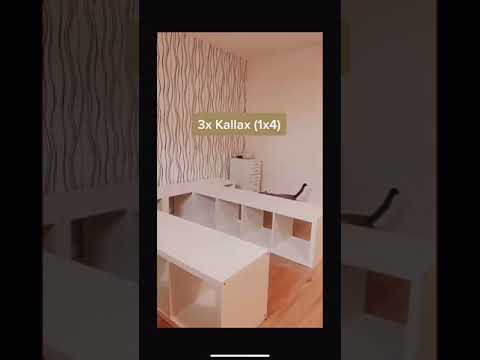
Budget friendly DIY that proves style doesn’t have to come with a hefty price tag! #Shorts #diy
 0:00:24
Ikea Bed Diy Home Decoration
 0:00:33
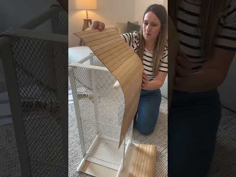
Easy IKEA Hack #shorts #diy #ikeahacks #diycrafts #ikeadiy #ikeahack #upcycling #diyhomedecor
 0:00:36
Fall dollar tree diy! Under $10 #diy #diyhomedecor #falldecor #falldecorating #dollartree
 0:12:42
Worst Oscilloscope in the World (DIY & Flip Dot Display)
 0:31:59
Budget-Friendly DIY Christmas Decorations You Can Make at Home - 2024
 0:00:52
Changing my life: day 7, new kitchen for $15
 0:00:47
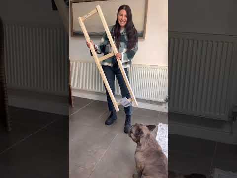
IKEA hack room divider! 🤯 Products linked below! #ad #shorts #upcycling #diy #dbpbrandambassador
 0:00:44
Ikea vase DIY! 😍 #ad #shorts #diy #terraclaypaint #dbpbrandambassador #ikeahack #ikea
 0:00:44
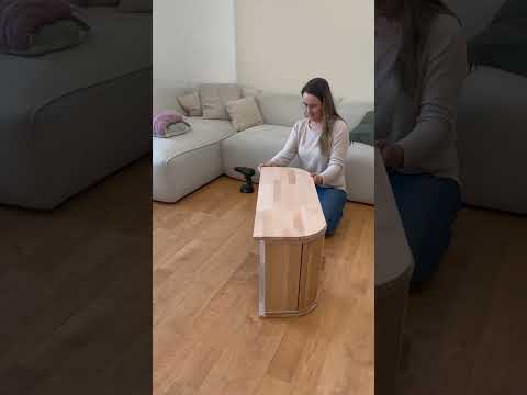
IKEA Möbel Hack #diyprojects #ikea #ikeahack #dekoidee #interior #diy #homedecor #easydiy #selberbau...
 0:00:51
Why do I Plane my Workbench? #diy #carpentry #woodwork #wood #woodworking #howto
 0:11:00
(DIY GREENHOUSE) How We Made Our Own Inexpensive Hoop House
 0:01:01
Was hättet ihr geschätzt? 💸🚐💰🎨 @LackStore #vanausbau #diy #shorts *ad
 0:00:50
4 budget friendly Ikea hacks! 😍 #shorts #ikeahack #ikeahacks #diy #dbpbrandambassador
 0:00:27
Want an outdoor sectional but don’t want to pay thousands?? #diy #build #outdoors
 0:00:46
IKEA Möbel Hack #diyprojects #ikea #ikeahack #dekoidee #interior #diy #homedecor #easydiy #selberbau...
 0:00:55
Budget-friendly fishing net made out of a ripped umbrella 🐠 #shorts #diy #reuse
 0:00:44
DIY RUSTIC BRANCH || HIGH-END DECOR ON A BUDGET #decorinspo #homedecor #diy
 0:18:03
Dollar Tree Products That Are 88% Cheaper Than Others
 0:11:06
How NOT to Build with Pavers- Why They FAIL! *DIY your own successful paver project
 0:01:01
Inside the DIY camper (lid closed)
 0:00:51
The Joinery Trick No One Teaches. #carpentry #diy #woodwork #wood #woodworking #tips #diywoodworking
 0:00:59
This Joint Shouldn't Work! (But it does) #carpentry #diy #woodwork #wood #woodworking #tips
Комментарии