filmov
tv
Home Automation System using multiple NodeMCU ESP8266 network with Blynk | IoT Projects 2021

Показать описание
In this IoT project, I have shown how to make the Home Automation System using multiple NodeMCU ESP8266 network with Blynk. with this smart home project, you can control multiple NodeMCUs from a single Blynk account. So you can use multiple ESP8266 for different rooms, and control them with Blynk App.
Discount Coupon Code:- JLCPCBcom
Download PCB Gerber file for this NodeMCU IoT based home automation project
During the tutorial video, I have covered the following topics:
00:17 How to control multiple NodeMCUs for different rooms with Blynk & Switches.
02:33 Required Components for this NodeMCU project.
02:47 Circuit diagram of multiple ESP8266 IoT-based Smart Home project.
04:22 How to configure the Blynk App.
05:55 Programming the ESP8266 NodeMCU with Arduino IDE
08:09 Connect home appliances with the smart relay module.
08:02 Controlling multiple NodeMCU control relays from Blynk.
Required Components for each room for this NodeMCU home automation
1. NodeMCU
2. 4-channel 5V SPDT Relay Module
3. Push Buttons
Amazon India Affiliate links:
Amazon United States Affiliate links:
Required Components for the NodeMCU control Relay Module PCB:
1. Relays 5v (SPDT) (4 no)
2. BC547 Transistors (4 no)
3. PC817 Optocuplors (4 no)
4. 510-ohm 0.25-watt Resistor (4 no) (R1 -- R4)
5. 1k 0.25-watt Resistors (5 no) (R5 -- R9)
6. LED 5-mm (5 no)
7. 1N4007 Diodes (4 no) (D1 -- D4)
8. Push Buttons (4 no)
9. Terminal Connectors
10. 5V DC supply
Download Code for this NodeMCU smart house automation project from the following article.
** (Important) Please don't connect both NodeMCUs with the laptop at the same time. And also use different 5V power supply for each NodeMCU. Otherwise, the relays turn on and off may take place.
** In code, you have to change only the virtual pins according to the NodeMCU numbers.
** You can use different WiFi networks for each NodeMCU, but the Authentication Token should be the same for all the NodeMCUs.
Our Previous ESP8266 NodeMCU Blynk project.
During the internet of things tutorial video, I have explained all the steps to make this ESP8266 home automation system with Blynk to control all the home appliances with and without internet. If the NodeMCU connected with WiFi then you can control the relays from anywhere in the world. And you can also monitor the real-time feedback in the Blynk IoT applications. So with this smart house project, you can convert any appliance to IoT devices and control them through the internet.
#internetofthings #esp8266 #Blynk
-------------------------------------------------------
Thanks For Watching...
✅ SUBSCRIBE ✅LIKE ✅SHARE ✅ COMMENTS
-------------------------------------------------------
Other useful IoT projects:
Latest NodeMCU projects playlist:
Latest ESP32 projects playlist:
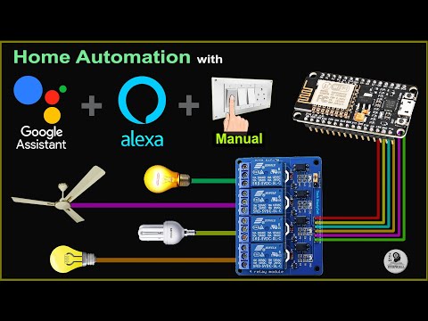
ESP32 Smart Home System with Amazon Alexa app & Manual Switches
WiFi Door Lock using ESP32 CAM & Blynk
Discount Coupon Code:- JLCPCBcom
Download PCB Gerber file for this NodeMCU IoT based home automation project
During the tutorial video, I have covered the following topics:
00:17 How to control multiple NodeMCUs for different rooms with Blynk & Switches.
02:33 Required Components for this NodeMCU project.
02:47 Circuit diagram of multiple ESP8266 IoT-based Smart Home project.
04:22 How to configure the Blynk App.
05:55 Programming the ESP8266 NodeMCU with Arduino IDE
08:09 Connect home appliances with the smart relay module.
08:02 Controlling multiple NodeMCU control relays from Blynk.
Required Components for each room for this NodeMCU home automation
1. NodeMCU
2. 4-channel 5V SPDT Relay Module
3. Push Buttons
Amazon India Affiliate links:
Amazon United States Affiliate links:
Required Components for the NodeMCU control Relay Module PCB:
1. Relays 5v (SPDT) (4 no)
2. BC547 Transistors (4 no)
3. PC817 Optocuplors (4 no)
4. 510-ohm 0.25-watt Resistor (4 no) (R1 -- R4)
5. 1k 0.25-watt Resistors (5 no) (R5 -- R9)
6. LED 5-mm (5 no)
7. 1N4007 Diodes (4 no) (D1 -- D4)
8. Push Buttons (4 no)
9. Terminal Connectors
10. 5V DC supply
Download Code for this NodeMCU smart house automation project from the following article.
** (Important) Please don't connect both NodeMCUs with the laptop at the same time. And also use different 5V power supply for each NodeMCU. Otherwise, the relays turn on and off may take place.
** In code, you have to change only the virtual pins according to the NodeMCU numbers.
** You can use different WiFi networks for each NodeMCU, but the Authentication Token should be the same for all the NodeMCUs.
Our Previous ESP8266 NodeMCU Blynk project.
During the internet of things tutorial video, I have explained all the steps to make this ESP8266 home automation system with Blynk to control all the home appliances with and without internet. If the NodeMCU connected with WiFi then you can control the relays from anywhere in the world. And you can also monitor the real-time feedback in the Blynk IoT applications. So with this smart house project, you can convert any appliance to IoT devices and control them through the internet.
#internetofthings #esp8266 #Blynk
-------------------------------------------------------
Thanks For Watching...
✅ SUBSCRIBE ✅LIKE ✅SHARE ✅ COMMENTS
-------------------------------------------------------
Other useful IoT projects:
Latest NodeMCU projects playlist:
Latest ESP32 projects playlist:
ESP32 Smart Home System with Amazon Alexa app & Manual Switches
WiFi Door Lock using ESP32 CAM & Blynk
 0:09:28
Home Automation System using multiple NodeMCU ESP8266 network with Blynk | IoT Projects 2021
 0:07:37
7 Best Home Automation Systems 2024
 0:13:56
Home Automation With Multiple Senosrs || Blynk 2.O || How To interface Multiple Senosrs with Nodemcu
 0:20:52
ESP32 ALL IN ONE home automation module for home assistant
 0:10:29
Smart Home Automation System with multiple ESP32 NodeMCU IoT network with Blynk | IoT Projects 2021
 0:10:52
Smart Home Automation Using Sensors #Version 2 || Tinkercad
 0:12:36
Door and Window Sensor Automation Ideas - Using Contact Sensors in Home Automation
 0:06:50
Smart Light Switches: I'm rethinking EVERYTHING!
 0:01:00
What Amazon and Microsoft Are Hiding from You in 2024?
 0:10:41
Smart Home with Google Assistant & Alexa using NodeMCU ESP8266 (Manual + Voice) | IoT Projects 2...
 0:09:35
Home Automation using ESP01 ESP8266 Tasmota Alexa control Relay - IoT Project 2023
 0:05:27
Home Automation System using ESP32 and Blynk 2.0 | Blynk ESP32 Relay Control
 0:18:45
£80k Smart Home System Setup, Ideas and Complete Demonstration
 0:16:23
IOT based home automation using Nodemcu | Step by step instructions [ESP8266 project]
 0:08:24
25 Home Automation Ideas: Ultimate Smart Home Tour (volume 2)
 0:12:26
How to Make a Complete 18 Channels Smart Automation Home System With Amazon Alexa | Hindi/Urdu
 0:19:49
Home automation that's private and local?! (Home Assistant Yellow)
 0:17:59
Home Automation Raspberry Pi Distribution Board DIY | IOT Project 2023
 0:00:31
Multiple Control Home Automation project for SALE! #esp32 #iot
 0:08:37
Smart Apartment Setup - 10+ Ideas that are EASY to move
 0:01:23
Ring Always Home Cam | The World’s First Flying Indoor Security Camera for Your Home | Ring
 0:16:07
Smart Home Automation Using Sensors #Version 3 || Tinkercad
 0:22:10
DIY Smart Home Appliance Control Via bluetooth
 0:05:47
Smart Home Hub or Nah? When and How to Use a Hub
Комментарии