filmov
tv
Arduino Tutorial #3 - Shift Registers (74HC595)
Показать описание
If you're curious about some of my ventures since the start of the channel, I've recently launched a newsletter with my thoughts on technology, business, entrepreneurship and more. You can check it out for free and subscribe if you're interested on my personal website:
Contribute:
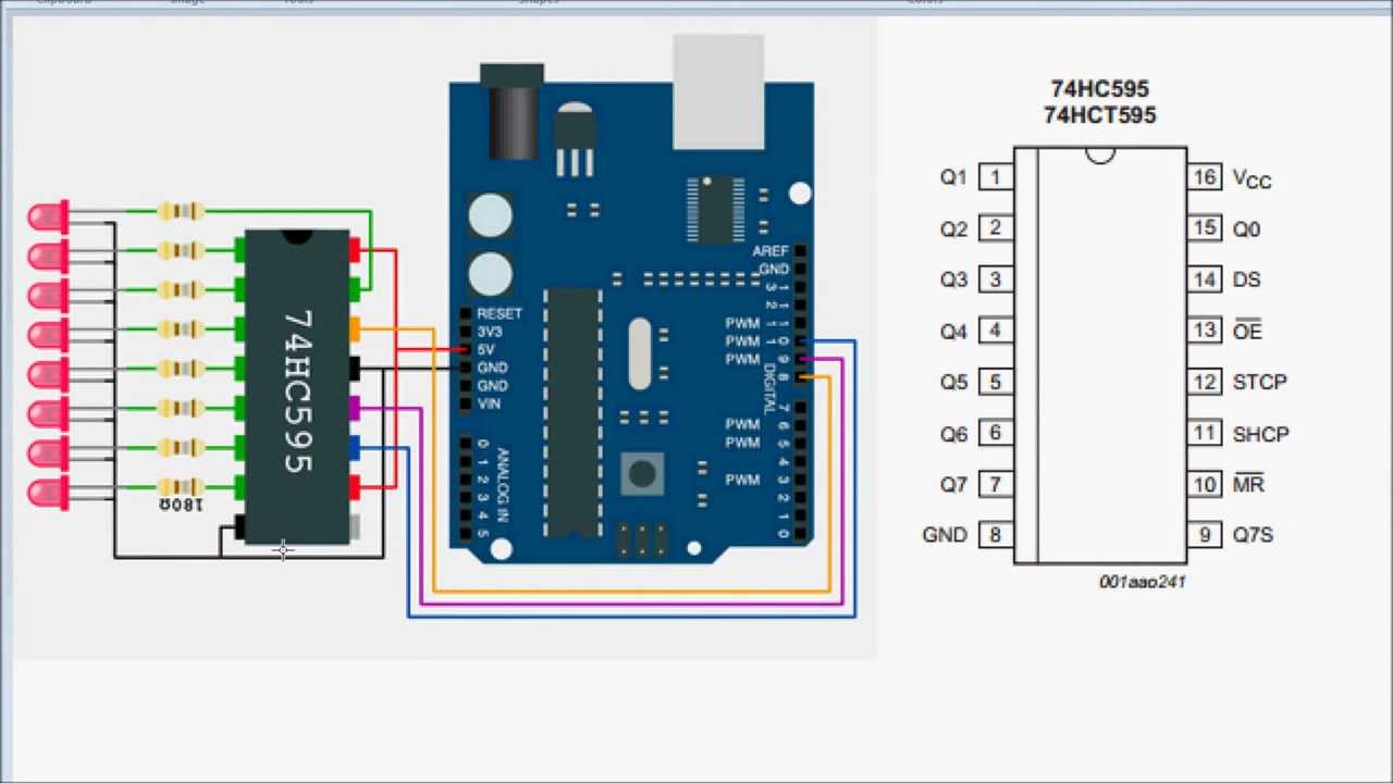
In the third Arduino Tutorial I discuss one of the many ways that you can expand your outputs on the Arduino. In this case, by using a shift register, I am able to use three Arduino pins to control 8 LEDs.
Search Terms & Keywords:
Getting Started Arduino
Beginner Arduino Tutorial
Arduino
Arduino Tutorial
Arduino Getting Started
Basic Arduino
Arduino Class
Arduino Hardware
Arduino Software
Arduino Code
Arduino Example
Arduino Project
Arduino How To
Arduino LED
Arduino Push Button
Push Button
Light Emitting Diaode
Atmega
Atmega328
Tutorial
Basic Hardware
Electronics
Electrical Engineering
Electronic Circuit
Simple Arduino Projects
Pulse Width Modulation
PWM
Analog Sensor
Temperature Sensor
Temperature Reading
RGB LED
PWM Output
PWM Tutorial
PWM explained
PWM guide
Shift Registers
Shift Register Tutorial
Contribute:
In the third Arduino Tutorial I discuss one of the many ways that you can expand your outputs on the Arduino. In this case, by using a shift register, I am able to use three Arduino pins to control 8 LEDs.
Search Terms & Keywords:
Getting Started Arduino
Beginner Arduino Tutorial
Arduino
Arduino Tutorial
Arduino Getting Started
Basic Arduino
Arduino Class
Arduino Hardware
Arduino Software
Arduino Code
Arduino Example
Arduino Project
Arduino How To
Arduino LED
Arduino Push Button
Push Button
Light Emitting Diaode
Atmega
Atmega328
Tutorial
Basic Hardware
Electronics
Electrical Engineering
Electronic Circuit
Simple Arduino Projects
Pulse Width Modulation
PWM
Analog Sensor
Temperature Sensor
Temperature Reading
RGB LED
PWM Output
PWM Tutorial
PWM explained
PWM guide
Shift Registers
Shift Register Tutorial
 0:14:07
Arduino Tutorial #3 - Shift Registers (74HC595)
 1:01:28
Arduino Tutorial 42: Understanding How to Use a Serial to Parallel Shift Register (74HC595)
 0:03:42
Arduino Tutorial 3: Inputs
 0:30:47
Arduino Tutorial 3: Understanding How Breadboards Work
 0:11:28
Arduino Tut. #3 - Extended - Shift Registers D flip-flops & Latches
 0:10:35
74hc595 with Arduino tutorial
 0:11:34
Arduino Tutorial 44: Understanding Logical Shift Left and Logical Shift Right with the 74HC595
 0:10:45
How to Add Outputs to an #Arduino using a Shift Register - The Learning Circuit
 0:04:18
SHIFT REGISTER ARDUINO tutorial | 74HC595 SHIFT REGISTER ARDUINO UNO [Code and circuit diagram]
 0:07:19
Arduino Shift Registers Extended (74HC595)
 0:07:04
74HC595 Shift Register (Arduino Tutorial Series)
 0:12:38
How to use 74HC595 Shift registers to control mulitple 7 segment displays
 0:03:45
How 74HC595 Shift Register Works ? | 3D animated 🔥
 0:00:36
3 x Arduino TI SN74HC595 Shift Register in Series
 0:11:11
Arduino Tutorial #3: Digital Inputs and Pull-Up Resitors
 0:09:41
Use Shift Registers to create more Inputs on Arduino Project! Tutorial
 0:09:45
INFINITE Pins for ARDUINO? | 74595 Shift Register
 0:40:38
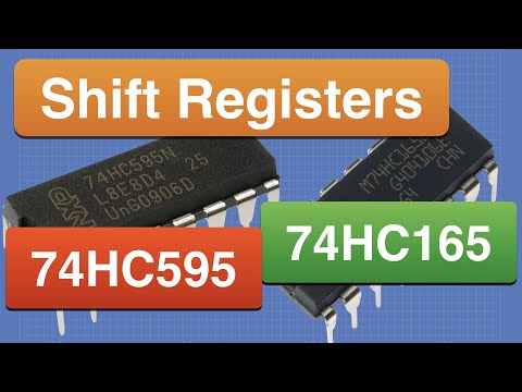
74HC595 & 74HC165 Shift Registers with Arduino
 0:04:34
Arduino Tutorial Italiano - Lo sketch - #3
 0:00:22
What engineering students actually do in labs 💀 #electronics #arduino #engineering
 0:00:21
learn Arduino programming in 20 seconds!! (Arduino projects)
 0:12:47
How to Add Multiple Inputs to an #Arduino using a Shift Register - The Learning Circuit
 0:05:04
HOW TO USE LOGIC LEVEL SHIFTER ON ARDUINO TO CONVERT CIRCUITS AND SENSORS FROM 5V TO 3.3V CIRCUITS
 0:05:02
how does a shift register work | Control 74hc595 with button without arduino
Комментарии