filmov
tv
how does a shift register work | Control 74hc595 with button without arduino

Показать описание
In this tutorial, you will learn about how to control a 74hc595 shift registor without an arduino. We are using 74hc595 ic and three push buttons to control 8 LEDs. I will also explain how it's works and pinout.
This is part 1 of the shift register series. In the next part, you will learn how to control the shift register by using arduino. We are use only 3 Arduino digital pins to control as many LEDs as you want. All you need a shift register ic.
So please keep watching this video to the end, and don't forget to hit like, share, and subscribe for more videos.
⭐Part 2: Arduino 74hc595 16 led with 18 effects
⭐Part 3: Arduino RGB led chaser
➖➖➖➖➖➖➖➖🔴Sponsor🔴➖➖➖➖➖➖➖➖
Buy cheap, quality electronic, and Arduino products.
➖➖➖➖➖➖➖➖➖➖➖➖➖➖➖➖➖➖➖➖➖
Topic :)
How to control shift registor with pushbutton without arduino.
what is a shift registor ( 74hc595 ) and how to control it
how does a 74hc595 shift register work.
*-*-*-*-*-*-*-*-*-*-*-*-*-*-*-*-*-*-*-*-*-*-*-*-*-*-*-*-*-*-*-*-*-*-*-*-*-*-*-*-*-*
Visit my blog to circuit of 74hc595 shift register.
Components Required for controlling shift register🛠🛠🛠
1. shift register 74hc595 for controlling the led
2. 3 Push Button to control the shift Registor
3. 8 LEDs as a output
4. 8 220ohm Resistor to protect the Led
5. 4 10k Resistor to reduce electronic noise from button.
6. jumper wire for connection
7. Breadboard to make prototype circuit.
-------------------------------------[ 🟧 BUSINESS 🟧 ]------------------------------------
⭐️If you want me to do custom projects or need my help in your projects,
so you can contact me.
*-*-*-*-*-*-*-*-*-*-*--*-*-*-*-*-*-*-*-*-*-*-*-*-*-*--*-*-*-*-*-*-*-*-*-*-*-*-*-*-*-*
Previous Video▶
Watch Next:✔
😊About us:-
Mr. ElectroUino is an education platform where we believe “Knowledge increases by sharing but not by saving” and it a community where we showcase you the best easy to follow tutorial on Engineering projects, Electronics, Robotics, DIY stuff, Arduino projects, Raspberry Pi, IOT project and many more such things that can bring out the best maker within you and help in making the World little smarter and techy.
#like #Share #Subscribe
*-*-*-*-*-*-*-*-*-*-*--*-*-*-*-*-*-*-*-*-*-*-*-*-*-*--*-*-*-*-*-*-*-*-*-*-*-*-*-*-*-*
Follow me on👍 : )
*-*-*-*-*-*-*-*-*-*-*-*-*-*-*-*-*-*-*-*-*-*-*-*-*-*-*-*-*-*-*-*-*-*-*-*-*-*-*-*-*-*-
Songs🎵🎵🎵
LYFO - HIGH [FREE DOWNLOAD]
JJD - Adventure [NCS Release]
Tobu - Hope [NCS Release]
Jarico - Island [NCS BEST OF]
------------------------------------.😎😎😎😎😎-------------------------------------------
© Mr.ElectroUino
#74hc595 #shiftRegistor #WithoutArduino #shiftRegistorbutton
 0:10:44
How Shift Registers Work - The Learning Circuit
 0:11:50
How Shift Registers Work!
 0:10:54
Introduction to Registers | What is Shift Register? Types of Shift Registers
 0:06:04
The Shift Register: Explained [74HC595]
 0:03:45
How 74HC595 Shift Register Works ? | 3D animated 🔥
 0:05:02
how does a shift register work | Control 74hc595 with button without arduino
 0:00:42
How shift registers work(Animation)
 0:12:33
Controlling a BIG LED Matrix?! How Shift Registers work! || EB#39
 0:05:49
Shift Registers
 0:05:47
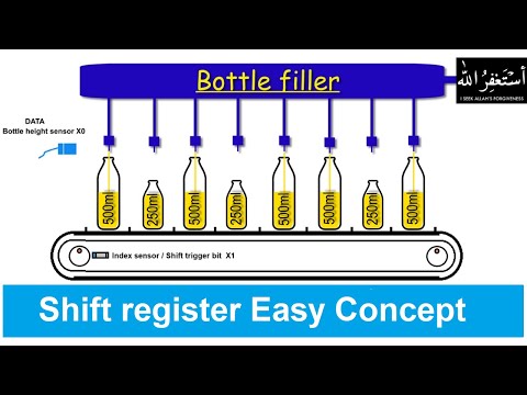
How does shift registers works ? PLC Programming Tutorials for Beginners
 0:40:38
74HC595 & 74HC165 Shift Registers with Arduino
 0:00:09
Parallel-in and Serial-out Shift Register
 0:13:51
Random Numbers with LFSR (Linear Feedback Shift Register) - Computerphile
 0:00:09
Serial-In Parallel-out Shft Register Using D Flip-Flop
 0:00:15
Shift register tutorial
 0:10:45
How to Add Outputs to an #Arduino using a Shift Register - The Learning Circuit
 0:05:41
Using A Shift Register To Manage A Front Control Panel On A Device - Simply Put
 0:10:09
How Shift Registers Work - 74HC595N
 0:00:08
74HC595 Shift Register IC | Arduino Shift Register LED Flasher | Arduino Shift Register Tutorial
 0:06:25
#1637 7495 74LS95 Shift Register
 0:09:49
How to Make a 4-bit Shift Register Circuit - The Learning Circuit
 0:00:13
Powering RGB LEDs using Parallel Shift Register!!! MUST WATCH!!
 0:15:16
Sequential Redstone Devices - LRR #8
 0:00:08
Arduino Shif Register Inputs | Arduino Shift Register Tutorial | Arduino multiple inputs and outputs
Комментарии