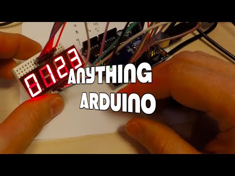
Arduino and the 4 digit 7 segment led display - Anything Arduino Ep 21

preview_player
Показать описание
In this arduino tutorial I explain how to work with the 4 digit 7 segment led display, and the difference between the four digit display and the one digit display, and how you can connect four one digit display to work just as the four digit one. I then show how to multiplex the common pins to be able to write different numbers to each digit. To see how the numbers are made watch Anything Arduino Episode 7 where I make the arduino sketch that we use and alter in this video.

Link to Anything Arduino Episode 7, working with the 7 segment LED display:

Рекомендации по теме
Комментарии
Автор

Nice work. I was able to get the "dot" to light up and alternate between the digits. You never mentioned using Pin 3, and hooking it up to Arduino pin 13. Gave me something to figure out. Thanks for that. #learningArduinoIsFun

remotecoderz
Автор

/*
Showing number 0-9 on a Common Anode 7-segment LED display
Displays the numbers 0-9 on the display, with one second inbetween.
A
---
F | | B
| G |
---
E | | C
| |
---
D
This example code is in the public domain.
*/

// Pin 2-8 is connected to the 7 segments of the display.

int pinA = 2;
int pinB = 3;
int pinC = 4;
int pinD = 5;
int pinE = 6;
int pinF = 7;
int pinG = 8;
int D1 = 9;
int D2 = 10;
int D3 = 11;
int D4 = 12;

// the setup routine runs once when you press reset:
void setup() {
// initialize the digital pins as outputs.
pinMode(pinA, OUTPUT);
pinMode(pinB, OUTPUT);
pinMode(pinC, OUTPUT);
pinMode(pinD, OUTPUT);
pinMode(pinE, OUTPUT);
pinMode(pinF, OUTPUT);
pinMode(pinG, OUTPUT);
pinMode(D1, OUTPUT);
pinMode(D2, OUTPUT);
pinMode(D3, OUTPUT);
pinMode(D4, OUTPUT);
}

// the loop routine runs over and over again forever:
void loop() {
digitalWrite(D1, HIGH);
digitalWrite(D2, LOW);
digitalWrite(D3, LOW);
digitalWrite(D4, LOW);
//0
digitalWrite(pinA, LOW);
digitalWrite(pinB, LOW);
digitalWrite(pinC, LOW);
digitalWrite(pinD, LOW);
digitalWrite(pinE, LOW);
digitalWrite(pinF, LOW);
digitalWrite(pinG, HIGH);
delay(1); // wait for a second

digitalWrite(D1, LOW);
digitalWrite(D2, HIGH);
digitalWrite(D3, LOW);
digitalWrite(D4, LOW);
//1
digitalWrite(pinA, HIGH);
digitalWrite(pinB, LOW);
digitalWrite(pinC, LOW);
digitalWrite(pinD, HIGH);
digitalWrite(pinE, HIGH);
digitalWrite(pinF, HIGH);
digitalWrite(pinG, HIGH);
delay(1); // wait for a second

digitalWrite(D1, LOW);
digitalWrite(D2, LOW);
digitalWrite(D3, HIGH);
digitalWrite(D4, LOW);
//2
digitalWrite(pinA, LOW);
digitalWrite(pinB, LOW);
digitalWrite(pinC, HIGH);
digitalWrite(pinD, LOW);
digitalWrite(pinE, LOW);
digitalWrite(pinF, HIGH);
digitalWrite(pinG, LOW);
delay(1); // wait for a second

digitalWrite(D1, LOW);
digitalWrite(D2, LOW);
digitalWrite(D3, LOW);
digitalWrite(D4, HIGH);
//3
digitalWrite(pinA, LOW);
digitalWrite(pinB, LOW);
digitalWrite(pinC, LOW);
digitalWrite(pinD, LOW);
digitalWrite(pinE, HIGH);
digitalWrite(pinF, HIGH);
digitalWrite(pinG, LOW);
delay(1); // wait for a second
/*
//4
digitalWrite(pinA, HIGH);
digitalWrite(pinB, LOW);
digitalWrite(pinC, LOW);
digitalWrite(pinD, HIGH);
digitalWrite(pinE, HIGH);
digitalWrite(pinF, LOW);
digitalWrite(pinG, LOW);
delay(1000); // wait for a second

//5
digitalWrite(pinA, LOW);
digitalWrite(pinB, HIGH);
digitalWrite(pinC, LOW);
digitalWrite(pinD, LOW);
digitalWrite(pinE, HIGH);
digitalWrite(pinF, LOW);
digitalWrite(pinG, LOW);
delay(1000); // wait for a second

//6
digitalWrite(pinA, LOW);
digitalWrite(pinB, HIGH);
digitalWrite(pinC, LOW);
digitalWrite(pinD, LOW);
digitalWrite(pinE, LOW);
digitalWrite(pinF, LOW);
digitalWrite(pinG, LOW);
delay(1000); // wait for a second

//7
digitalWrite(pinA, LOW);
digitalWrite(pinB, LOW);
digitalWrite(pinC, LOW);
digitalWrite(pinD, HIGH);
digitalWrite(pinE, HIGH);
digitalWrite(pinF, HIGH);
digitalWrite(pinG, HIGH);
delay(1000); // wait for a second

//8
digitalWrite(pinA, LOW);
digitalWrite(pinB, LOW);
digitalWrite(pinC, LOW);
digitalWrite(pinD, LOW);
digitalWrite(pinE, LOW);
digitalWrite(pinF, LOW);
digitalWrite(pinG, LOW);
delay(1000); // wait for a second

//9
digitalWrite(pinA, LOW);
digitalWrite(pinB, LOW);
digitalWrite(pinC, LOW);
digitalWrite(pinD, HIGH);
digitalWrite(pinE, HIGH);
digitalWrite(pinF, LOW);
digitalWrite(pinG, LOW);
delay(1000); // wait for a second
*/
}

KontrolRageBeats
Автор

great vid! . .thanks - but why do you not use resistors before the LED?!

irminsul
Автор

Definitely better than most tutorials on YouTube

chernoblyat
Автор

Hello, Why you don't use resistors between segments and arduino?

grzegorzdabrowski
Автор

Just awesome. The video was so detailed. It was so easy for me to follow along because of how precise the video was. Thank you so much. Very greatly appreciated! P.S. I subbed!

godsonshaiju
Автор

The one thing is missing to show how to display a variable which was generated as a result of some maths in code.

bogu
Автор

Good work friend ❤😉👍👏👏👏👏👏subscribed Brazil

arduinomaquinas
Автор

Love the video, the explanation was perfect, the speed was perfect, and you're easy to understand. Thank you for taking the time to teach this. Thumbs up!

techsguild
Автор

3 digit 7-segment display circuit and how to connect it on the breadboard to count from 0 to 100

AtoPrince
Автор

hello! this tutorial really helped me build! Is there a place where this code is posted? I wanna test it out with the clock

SickCookie
Автор

Great job!!!! You made it so easy for me to understand!! Thanks a lot for the video!!!

AHElectronics
Автор

Do you need to use dupont wires or can you the normal wires?

teejn
Автор

I really liked the way you are making the things simpler but when I have done in the same manner as you showed in the video but it is not getting any output and from where is this 4 in 7 segment getting power as you have not connected any supply to it

nihadabbikar
Автор

Just a quick note, as I just did this and wanted to see how others also did it.
It is better to turn all the digit pins all off before setting the next number's segments. Then set the segments you want before turning on that digit.
You'll notice a faint 0 bleeding into digit 1, and a faint 1 into digit 2 etc. because you are turning on digit 1 before you set the segments for the 1, and the previous 0 segments are still on for a few microseconds!

ChrisMayer-uitb
Автор

Kristian this video helped greatly, although I was wondering if you could assist by using this same code, but adding in a way to display numbers that are entered from the serial monitor?

Abdul
Автор

Very nice tutorial, especially explaining that 12 pins of a 4 digit display are the same as those of 4 individual displays.

leef_me
Автор

Thanks. I am trying to make a video game device like a nintendo game and watch using arduino. I found this very helpful.

lordhendrickson
Автор

Do we need to also put capacitors for this display?

chef
Автор

Very nice work. Easy to understand. Thank you

hasanyuksel