filmov
tv
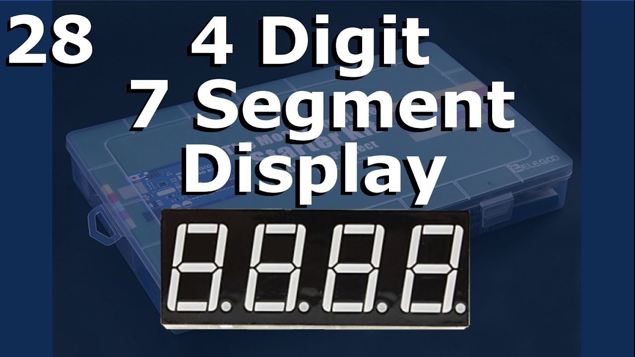
Lesson 28 - 4 Digit 7 Segment Display
Показать описание
Four Digit Seven Segment Display Module. Demonstrate the Elegoo sketch provided in the tutorial covering the display module, show it shortcomings and provide a revised sketch to properly control a 4-digit 7-segment display with 74HC595 shift register IC and four PN2222 transistors. A beginner's guide to the Most Complete Starter Kit by Elegoo.
Hello everyone, I'm Rick the Tech Enthusiast here with the next Elegoo Lesson. This is the next lesson on my Arduino UNO Series covering the Most Complete Starter Kit by Elegoo. I try to follow the included tutorial and will point out any changes or corrections as I find them.
As mentioned before, I purchased this Elegoo starter kit and Elegoo isn't sponsoring me. I just thought it would be fun to do a video of each Lesson as I was learning the Arduino environment.
We’ll need a few things from your Elegoo Arduino UNO kit. I’ll list the items below. In this lesson we’re going to check out the 4 Digit 7 Segment Display Module, 5641AS common cathode type. I’ll step through the Elegoo provided tutorial, briefly explain the code, the circuit, and some of the issues. Then I present my revised circuit and sketch that properly demonstrates the functionality. I hope you enjoy it.
Parts you’ll need for the tutorial:
* Elegoo UNO R3 board
* The 74HC595 shift register IC
* 4-digit, 7-segment display
* Four 220-ohm resistors
* The breadboard
* A bunch of male-to-male jumper wires
To build the revised circuit, add the following:
* Four 220-ohm resistors
* Four 5K-ohm resistors
* Four PN2222 transistors
The next lesson will be Lesson 29: DC Motors
Links:
Various Parts can be found: (Note these are Amazon Associates links)
(Full Disclosure: I get a little credit/$ if you purchase a linked item.)
Software:
Affiliate Links that Help my channel:
This is another video for my Arduino tutorial series. If you like the series, be sure to rate and subscribe.
Thanks for watching
 0:29:08
Lesson 28 - 4 Digit 7 Segment Display
 0:05:09
Eureka Math Grade 1 Module 4 Lesson 28
 0:12:21
lesson 28 homework module 4 grade 1
 0:08:54
Eureka Math Grade 5 Module 4 Lesson 28
 0:11:16
lesson 28 homework module 4 grade 2
 0:08:07
Module 4 Lesson 28
 0:18:35
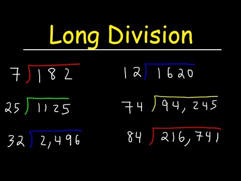
Long Division Made Easy - Examples With Large Numbers
 0:08:43
Gr. 1 Module 4 Lesson 28
 0:01:02
(Arduino) ELEGOO The Most Complete Starter Kit - Lesson 28「Four Digital Seven Segment Display」
 0:01:59
Grade 1 Module 4 Lesson 28
 0:02:06
Grade 1 Module 4 Lesson 28
 0:08:31
4 Digit 7 segment display using Arduino
 0:04:46
Eureka Math Grade 1 Module 4 Lesson 28
 0:11:28
Long Division: Dividing 4-Digit Numbers by 2-Digit Numbers
 0:08:25
Eureka Math Grade 4 Module 3 Lesson 28
 0:04:58
Code.org Lesson 28.4 Project - Design a Game | Tutorial with Answers | C.S. Discoveries Unit 3
 0:45:52
Year 4 Math Lesson 28
 0:04:49
4-digit by 2-digit | Multiplication | Maths with Mrs. B
 0:04:29
Saxon Math 4 Lesson 28
 0:25:14
LESSON 28: Tutorial for Programming Software Interrupts on Arduino
 0:08:08
Grade 2 Module 4 Lesson 28 Concept Development NEW
 0:14:30
Math Lesson 28 Session 4 Google Slides: Adding Two-Digit and One Digit Numbers
 0:09:07
Engage NY Module 3 Lesson 28
 0:01:35
Expert: Lesson 28 Exit Ticket Grade 1
Комментарии