filmov
tv
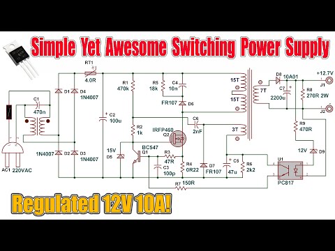
How a Switching Power Supply Works and How to Make One

Показать описание
Circuit Link:
In today's video I'll be showing you how to make a Switching Power Supply with a detailed description about the working of a practical Circuit. It's a simple yet very capable Self-Oscillating Flyback Switch Mode Power Supply which has a Regulated output of 12Volts and a Current capacity of up to 10Amps.
As always, thank you for your time. Don't forget to Like, Share with your friends, check some of my other videos and SUBSCRIBE for more!
#Power Supply #SMPS #electronics
Website:
 0:11:21
Understanding Switching Mode Power Supplies
 0:26:17
#772 Basics: Switching Power Supplies (part 1 of 2)
 0:13:58
Basics of Switched Mode Power Supplies (SMPS) - Charge Pumps, Switching Elements, Types
 0:16:38
How SMPS works | What Components We Need? Switched Mode Power Supply
 0:01:35
What is a Switching Power Supply?
 0:55:59
How A Switching Power Supply Works
 0:10:29
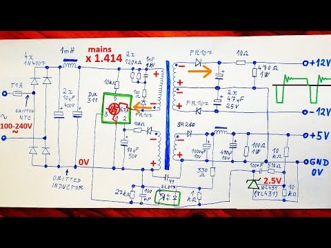
How does a modern Power Supply work?! (230V AC to 5/12V DC) DIY Flyback Converter!
 0:07:14
How a Switching Power Supply Works and How to Make One
 0:22:21
Full Build: Simple True-Sine Turntable Motor Power Supply, based on Arduino and MagicQuartz
 0:30:48
How Does a Switching Power Supply Work 1 (schematic, explanation, example, modifications)
 0:10:47
A Noise-Free DIY Switching Power Supply - How Hard Can It Be?
 0:03:10
Linear vs Switching DC Power Supplies - What's the Difference?
 0:00:32
Switching Mode Power Supply SMPS S-35-12AC-DC Single Output Enclosed power supply; Output 12VDC
 0:10:13
How Does a Switching Power Supply Work 2 (measurements)
 0:02:22
Switching VS Linear Power Supplies - A Galco TV Tech Tip | Galco
 0:01:00
Linear vs. Switching Power - Collin’s Lab Notes #adafruit #collinslabnotes
 0:02:07
How to wire a LED Power Supply (Switching Power Supply)
 0:10:46
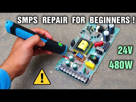
24 Volt 480W SMPS Power Supply Repair - Step By Step
 0:08:29
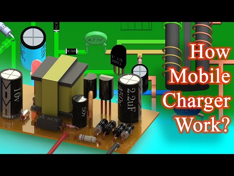
How mobile phone charger works ? | SMPS Switch mode power supply
 0:06:34
#773 Basics: Switching Power Supplies (part 2 of 2)
 0:06:30
How does a mobile charger work? SMPS with Opto-Coupler.
 0:10:39
Power Supplies Explained
 0:29:45
Switch Mode Power Supply Repair, SMPS
 0:00:16
SMPS power supply Repair 🔥🔥💡💡😱#shorts #youtubeshorts #viral
Комментарии