filmov
tv
#250 Universal Power Source (UPS) for only 2$. Is this possible? (Raspberry Pi, Arduino, ESP32)

Показать описание
Uninterruptable power sources or UPS for your Raspberry Pi, Arduino, or ESP microcontroller usually are quite expensive and also do not always work. When I found these small 2 dollar modules, I asked myself: Can we use them as a UPS? Or are they just junk and false promises? Time for a closer look!
From time to time viewers ask how they should power their projects, especially with batteries. Today we will take a look at this small module and find out if it is any good, how it compares with Power Banks, and where it fits in the “energy supply chain.”
Links:
If you want to support the channel, please use the links below to start your shopping. No additional charges for you, but I get a commission (of your purchases the next 24 hours) to buy new stuff for the channel
Please do not try to Email me or invite me on LinkedIn. These communication channels are reserved for my primary job
#250 Universal Power Source (UPS) for only 2$. Is this possible? (Raspberry Pi, Arduino, ESP32)
 0:00:23
How to make 5V, 9V, 12V, 15V, 18V power supply #shorts #diy #viral
 0:00:12
Lipo 4s under/over volt super explosion💥💥
 0:00:21
Charge old UPS battery (lead acid) with High Voltage experiment
 0:00:28
universal 12V Car Motorcycle Battery Charger #ideas
 0:00:14
Best battery charging hack for dead batteries!!!!
 0:01:04
Waveshare Uninterruptible Power Supply(UPS) Module, Support Charge And Power Output, 3S&5V 5A Ou...
 0:00:06
Computer power supply diagram #Atx main connector ,atx power supply ,PC smps
 0:00:14
Spotpear Raspberry Pi PICO UPS Power Module 18650 lithium battery UPS uninterruptible power supply
 0:02:48
Uninterruptible Power Supply | UPS for Arduino | ESP
 0:00:15
free energy solar penal 750w installation Invt solar inverter
 0:00:37
DC TO DC Booster Module Test || 3.7 Volt To 40 Boost || @harshitexperiment3003||
 0:00:16
4000W 12V to 220V LED Car Power Inverter Converter Charger Adapter Dual USB Voltage
 0:08:27
Li-Ion battery to 5/9/12/15V UPS/Power Supply based on PTN04050 Module
 0:00:25
Testing GY6 regulator 4wires #motorcycle #parts
 0:00:15
E bike charger repairing scooty charger electronic scooty #iccharger #electronic #scooty #charger
 0:00:29
AMD Sempron Cpu processor .Removing pins For Gold Recovery . gold recovery from cpu Processors
 0:00:15
12 Volt Operated Small 200 Watt Dc To Ac Converter @B.techRaghav
 0:00:16
UPS Transformer Connected with Inverter 121 kit practice class ABC Tech institute call 9540879879
 0:00:18
How to reset laptop batteries
 0:15:08
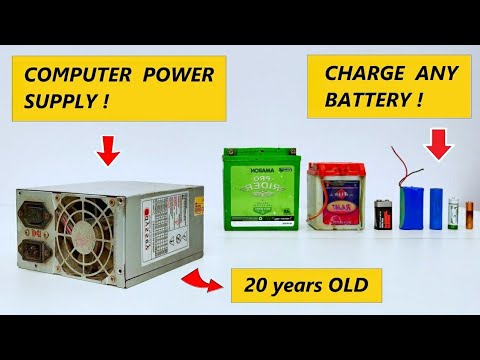
20 Amp Battery Charger with Computer Power Supply - 220v AC to 1.5v / 3v / 6v / 9v / 12v / 24v DC
 0:00:11
How to make a inverter. 12v to 250v #shortvideo
 0:13:53
Raspberry Pi Waveshare UPS
 0:08:01
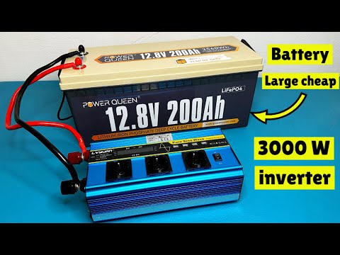
12v inverter 3000W test with maximum continuous discharging current 200ah battery
Комментарии